Posted Aug 27, 2022
Delayed Opening Action of Pneumatic Butterfly Valves
In a nuclear power plant, the pneumatic butterfly valve fails to open many times during the operation of the unit (the operation specification requires the opening time of the valve to be ≤120 s). At the beginning of valve opening, there is no action within 2 ~ 3 min. After the valve starts to operate, it can reach the fully open state within 30 ~ 40 s, but the valve is jammed at 20% ~ 40% opening. After testing, all parts of the valve run well, and there are no body faults such as jams and damage. In order to completely eliminate the valve opening delay and jam failure, a series of analyses, calculations and related tests were carried out on the valve and system, to find out the causes of valve failure, and to formulate the valve improvement scheme.
structural property
The valve is composed of a rubber-lined butterfly valve and a pneumatic device (Figure 1). A rubber-lined butterfly valve is composed of the valve body, butterfly plate, valve seat and valve stem, etc. The valve is sealed by the interference between the butterfly plate and the rubber valve seat. The pneumatic device is a fork-type single-acting cylinder, with air intake at the cylinder side, the piston pushing the fork to rotate, the output torque closing the valve, and compressing the spring to store energy. The air intake at the cylinder side is stopped, and the spring is reset, pushing the piston to drive the fork to rotate, and the output torque opens the valve. The butterfly valve has a nominal size of DN600 and a working pressure of 1. 2MPa.
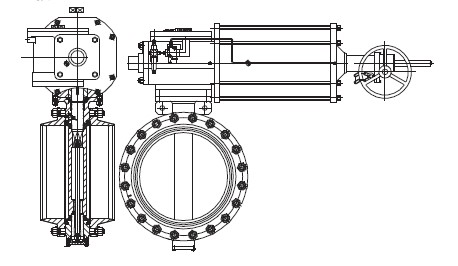
Fig. 1 pneumatic rubber lining wafer butterfly valve
Calculation and analysis
According to the actual working conditions of the valve, the opening torque of the butterfly valve is calculated and measured by theoretical calculation and experiment.
1. Calculation
According to the theoretical calculation, the maximum opening torque of the valve is about 4 200N·m, and the designed output torque of the pneumatic actuator of the valve is 4 106-7 035 N m. Under normal circumstances, the actual torque should be less than the theoretical calculation value, and the valve torque can meet the normal opening of the valve.
2. Dynamic test
Install the valve on a straight pipe section of the test bench, and use the test pump to circulate the flow rate of this pipe section under 1. 2 MPa, and measure the torque change of the valve. At the moment of opening the rubber-lined butterfly valve, due to the influence of the friction torque of the sealing surface, the torque is larger. After the butterfly plate is opened for 20, it has completely separated from the sealing surface, and the torque of the valve is obviously reduced. Keep the valve closed for 20 d under the pressure of 1. 2 MPa, and start the pump for flow circulation and comparative test. The measured results show that the maximum torque of valve opening occurs between the butterfly plate and the valve. When the sealing surfaces are combined (that is, when there is static friction resistance), the measured maximum torque is < 2 500 N m. Less than the designed output torque of the pneumatic actuator of the valve 4 106-7 035 N m. Therefore, it can be judged that the valve design meets the requirements of actual working conditions. Failure at the site is due to other factors not considered in the design.
3. Analysis
Based on the modeling analysis of the actual situation on the spot, it is found that the pipeline system where the valve is located is complex, the distance between the front and rear bends is short, the turbulence is strong, and the hydrodynamic moment exceeds the design value, so the medium has a great impact on the butterfly plate. Theoretical calculation and analysis of valve dynamic test results show that the reason why the valve cannot be opened is that the hydrodynamic torque of the system exceeds the design requirements. After research, there are three solutions. One is to change the system pipeline and reduce the hydrodynamic torque of the valve. The second is to increase the output torque of the pneumatic actuator of the valve and overcome the hydrodynamic torque of the valve. The third is to reduce the static resistance of the valve and use more output torque to overcome the hydrodynamic torque of the valve.
4 improvement
Because of the system layout and other reasons, it is difficult to change the pipeline. In order to ensure the reliability of the valve, the combination of the two and three schemes is adopted on-site, that is, replacing the cylinder spring to increase the output torque of the valve and reducing the interference of the valve seat seal to reduce the static resistance of the valve, so as to eliminate the failure that the valve cannot be opened. When the valve is stuck in 20 %-40% of the cases, the upper and lower valve stems are added with tie rods to reduce the influence of system pressure on the deviation of the upper and lower valve stems.
Reduce the sealing interference
Reducing the sealing interference can reduce the static resistance when the valve is opened and closed, and the unilateral interference between the butterfly plate and the valve seat is reduced from 2. 0 mm to 1. 6mm, which effectively reduces the driving torque of the valve. In order to verify the feasibility of the scheme, a prototype was developed. Except for the reduction of the sealing interference of the prototype, other parameters have little change. The original valve and the prototype valve were tested with no load and 1.76 MPa opening and closing torque. The test method is to measure the valve opening torque value after the butterfly plate is closed to the fully closed position (Table 1).
Table 1 butterfly valve opening torque test (the data is the average value of multiple tests) n m
Test data show that reducing the sealing interference reduces the valve torque by about 600 N·m under no-load conditions, and the valve torque by about 1500 N·m under 1. 76 MPa conditions. From the analysis of test results, the valve opening torque can be effectively reduced after the sealing interference is reduced.
Increase rod mechanism of the valve stem
A pull rod mechanism is added to the upper and lower valve stems to reduce the influence of system pressure on the offset of the upper and lower valve stems, improve the coaxiality of the upper and lower valve stems, and eliminate the blockage in the middle position caused by the misalignment of the valve stems. A small ball structure is designed at the joint between the lower valve stem and the butterfly plate, which can position and prevent the lower valve stem and the butterfly plate from rotating, and the upper and lower valve stems can rotate synchronously to ensure that the threads at the joint between the upper and lower valve stems will not loosen.
Cylinder improvement
Considering the space limitation of the site, only the piston cylinder and the matched spring are improved. After calculation, the cylinder diameter D = 450 mm, and the effective number of turns of the outer spring is 10. 5, the total number of turns 12, the full compression pressure 20. 1 kN, the effective number of turns of the innerspring 10. 5, the total number of turns 12, and the full compression pressure 20. 2 kN are selected. After the improvement, the maximum opening torque of the cylinder increases by 1. 4 times, reaching 7 550 N m, and the designed safety factor reaches 1. 75, which can avoid the valve jam caused by turbulence, vibration and bearing wear.
Conclusion
After the improvement of the rubber-lined butterfly valve, after field application, the 120s delay in the opening of the valve completely disappeared, the valve could be opened within 30-50 s, and the 20% ~ 40% opening jam completely disappeared, and the valve was verified as qualified. After replacing a large number of similar valves in the system, its performance is good, and there is no jam or delay in opening, which guarantees the normal operation of the system.
structural property
The valve is composed of a rubber-lined butterfly valve and a pneumatic device (Figure 1). A rubber-lined butterfly valve is composed of the valve body, butterfly plate, valve seat and valve stem, etc. The valve is sealed by the interference between the butterfly plate and the rubber valve seat. The pneumatic device is a fork-type single-acting cylinder, with air intake at the cylinder side, the piston pushing the fork to rotate, the output torque closing the valve, and compressing the spring to store energy. The air intake at the cylinder side is stopped, and the spring is reset, pushing the piston to drive the fork to rotate, and the output torque opens the valve. The butterfly valve has a nominal size of DN600 and a working pressure of 1. 2MPa.
Fig. 1 pneumatic rubber lining wafer butterfly valve
Calculation and analysis
According to the actual working conditions of the valve, the opening torque of the butterfly valve is calculated and measured by theoretical calculation and experiment.
1. Calculation
According to the theoretical calculation, the maximum opening torque of the valve is about 4 200N·m, and the designed output torque of the pneumatic actuator of the valve is 4 106-7 035 N m. Under normal circumstances, the actual torque should be less than the theoretical calculation value, and the valve torque can meet the normal opening of the valve.
2. Dynamic test
Install the valve on a straight pipe section of the test bench, and use the test pump to circulate the flow rate of this pipe section under 1. 2 MPa, and measure the torque change of the valve. At the moment of opening the rubber-lined butterfly valve, due to the influence of the friction torque of the sealing surface, the torque is larger. After the butterfly plate is opened for 20, it has completely separated from the sealing surface, and the torque of the valve is obviously reduced. Keep the valve closed for 20 d under the pressure of 1. 2 MPa, and start the pump for flow circulation and comparative test. The measured results show that the maximum torque of valve opening occurs between the butterfly plate and the valve. When the sealing surfaces are combined (that is, when there is static friction resistance), the measured maximum torque is < 2 500 N m. Less than the designed output torque of the pneumatic actuator of the valve 4 106-7 035 N m. Therefore, it can be judged that the valve design meets the requirements of actual working conditions. Failure at the site is due to other factors not considered in the design.
3. Analysis
Based on the modeling analysis of the actual situation on the spot, it is found that the pipeline system where the valve is located is complex, the distance between the front and rear bends is short, the turbulence is strong, and the hydrodynamic moment exceeds the design value, so the medium has a great impact on the butterfly plate. Theoretical calculation and analysis of valve dynamic test results show that the reason why the valve cannot be opened is that the hydrodynamic torque of the system exceeds the design requirements. After research, there are three solutions. One is to change the system pipeline and reduce the hydrodynamic torque of the valve. The second is to increase the output torque of the pneumatic actuator of the valve and overcome the hydrodynamic torque of the valve. The third is to reduce the static resistance of the valve and use more output torque to overcome the hydrodynamic torque of the valve.
4 improvement
Because of the system layout and other reasons, it is difficult to change the pipeline. In order to ensure the reliability of the valve, the combination of the two and three schemes is adopted on-site, that is, replacing the cylinder spring to increase the output torque of the valve and reducing the interference of the valve seat seal to reduce the static resistance of the valve, so as to eliminate the failure that the valve cannot be opened. When the valve is stuck in 20 %-40% of the cases, the upper and lower valve stems are added with tie rods to reduce the influence of system pressure on the deviation of the upper and lower valve stems.
Reduce the sealing interference
Reducing the sealing interference can reduce the static resistance when the valve is opened and closed, and the unilateral interference between the butterfly plate and the valve seat is reduced from 2. 0 mm to 1. 6mm, which effectively reduces the driving torque of the valve. In order to verify the feasibility of the scheme, a prototype was developed. Except for the reduction of the sealing interference of the prototype, other parameters have little change. The original valve and the prototype valve were tested with no load and 1.76 MPa opening and closing torque. The test method is to measure the valve opening torque value after the butterfly plate is closed to the fully closed position (Table 1).
| project | The interference of the original butterfly valve is 2. 0 mm | The interference of the original butterfly valve is 2. 0 mm |
| No-load | 2 264 | 1 680 |
| 1. 76 MPa open | 4 728 | 3 226 |
Table 1 butterfly valve opening torque test (the data is the average value of multiple tests) n m
Test data show that reducing the sealing interference reduces the valve torque by about 600 N·m under no-load conditions, and the valve torque by about 1500 N·m under 1. 76 MPa conditions. From the analysis of test results, the valve opening torque can be effectively reduced after the sealing interference is reduced.
Increase rod mechanism of the valve stem
A pull rod mechanism is added to the upper and lower valve stems to reduce the influence of system pressure on the offset of the upper and lower valve stems, improve the coaxiality of the upper and lower valve stems, and eliminate the blockage in the middle position caused by the misalignment of the valve stems. A small ball structure is designed at the joint between the lower valve stem and the butterfly plate, which can position and prevent the lower valve stem and the butterfly plate from rotating, and the upper and lower valve stems can rotate synchronously to ensure that the threads at the joint between the upper and lower valve stems will not loosen.
Cylinder improvement
Considering the space limitation of the site, only the piston cylinder and the matched spring are improved. After calculation, the cylinder diameter D = 450 mm, and the effective number of turns of the outer spring is 10. 5, the total number of turns 12, the full compression pressure 20. 1 kN, the effective number of turns of the innerspring 10. 5, the total number of turns 12, and the full compression pressure 20. 2 kN are selected. After the improvement, the maximum opening torque of the cylinder increases by 1. 4 times, reaching 7 550 N m, and the designed safety factor reaches 1. 75, which can avoid the valve jam caused by turbulence, vibration and bearing wear.
Conclusion
After the improvement of the rubber-lined butterfly valve, after field application, the 120s delay in the opening of the valve completely disappeared, the valve could be opened within 30-50 s, and the 20% ~ 40% opening jam completely disappeared, and the valve was verified as qualified. After replacing a large number of similar valves in the system, its performance is good, and there is no jam or delay in opening, which guarantees the normal operation of the system.
News
Industry News
Back to List
