Nondestructive Testing Methods for OCTG Pipe Defect Detection
Magnetic flux leakage (MFL) testing is a nondestructive testing (NDT) technique used to detect defects in ferromagnetic materials. It relies on the high magnetic permeability of these materials, which allows magnetic flux to remain largely confined within the material when it is subjected to an external magnetic field or retains residual magnetism. When a defect is present at or near the material surface, it creates a localized increase in magnetic reluctance. This discontinuity distorts the magnetic flux path, causing part of the magnetic flux to escape from the material into the surrounding air and form a leakage magnetic field. The resulting field can be detected by magnetic sensors to identify defects. The principle of MFL testing is illustrated in Figure 3.
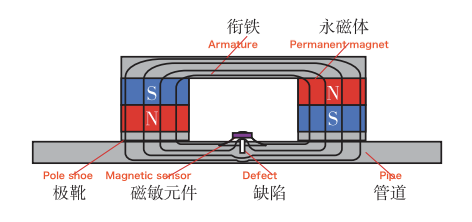
Figure 3. Schematic illustration of the MFL testing principle
A typical magnetic flux leakage (MFL) testing system consists of four main components:
- Magnetizer
- Magnetic field sensors
- Signal processing unit
- Analog-to-digital converter (ADC)
The magnitude of the leakage magnetic flux generated by a defect is inversely related to its depth. The closer a defect is to the surface, the greater the proportion of magnetic flux that leaks into the surrounding air. Because the sensors are typically positioned on the material surface, MFL testing is significantly more sensitive to surface and near-surface defects than to deep-seated defects. The relative orientation of the magnetization direction and the crack is critical to detection effectiveness. When the magnetization direction is perpendicular to the crack, a distinct leakage magnetic flux signal is generated at the crack. However, when the magnetization direction intersects the crack at an angle, the resulting leakage signal is difficult for the sensors to detect directly. This limitation restricts the ability of conventional unidirectional magnetization MFL systems to detect defects with different orientations. During high-speed inspection, motion-induced eddy currents can also significantly affect MFL results. Figure 4 shows the distributions of motion-induced eddy currents and magnetic fields. As the test specimen moves, it cuts across the magnetic flux lines, inducing eddy currents within the specimen. These motion-induced eddy currents interfere with the accuracy of MFL testing. Understanding this phenomenon is essential for interpreting signals under high-speed inspection conditions.
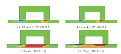
(a) Motional eddy current distribution at 0.5 m/s (b) Motional eddy current distribution at 2 m/s
(c) Magnetic field distribution at 0.5 m/s (d) Magnetic field distribution at 2 m/s
Figure 4. Distributions of motion-induced eddy currents and magnetic fields
Magnetic flux leakage (MFL) testing is primarily used to detect surface and near-surface defects in ferromagnetic OCTG Pipes, including corrosion pits, cracks, wall thinning, and wear damage, which distort the magnetic flux distribution within the material. However, its application to OCTG Pipe integrity assessment presents several challenges, including fluctuations in probe lift-off distance during wellhead inspection and the quantitative assessment of non-uniform wall-thickness corrosion. Researchers have conducted systematic studies to address these challenges.
Regarding theoretical modeling, Ma et al. used ANSYS to develop a three-dimensional finite element model of the magnetic field distribution in drill pipes under excitation, providing a theoretical basis for optimizing drill pipe inspection systems. Wu et al. investigated the effects of non-uniform wall thickness on MFL signal characteristics in OCTG Pipes affected by corrosion during service. They also experimentally validated their theoretical model, providing a basis for quantitatively assessing complex corrosion patterns. In addition to these modeling studies, researchers have proposed various solutions to the practical challenge of maintaining a stable probe lift-off distance during wellhead inspections.
Based on the principle of magnetic flux concentration, Ma et al. designed a novel MFL probe that maintains stable signal strength over a wide range of lift-off distances. Wu et al. proposed a drill pipe MFL inspection method designed to accommodate lift-off variations. The system uses a flexible follower mechanism that allows the probe to adjust its position in response to drill pipe oscillations, effectively reducing lift-off fluctuations caused by pipe movement at the wellhead. To inspect regions with complex geometries, Wang et al. developed a flexible alternating-current magnetic flux leakage (AC-MFL) probe for the internal and external upset transition zones of drill pipes, which are susceptible to stress concentration and damage. The probe integrates the exciter and sensors into a single unit, allowing it to closely follow curved surfaces during near-field inspection. This design enables highly sensitive defect detection in drill pipe transition zones, and its effectiveness in inspecting geometrically complex regions has been verified experimentally. Figure 5 shows the MFL inspection equipment used for wellhead drill pipes and representative inspection signals.
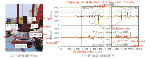
(a) Drill pipe MFL inspection equipment (b) Typical MFL signals from drill pipe inspection
Figure 5 Wellhead drill pipe MFL inspection equipment and typical signals
MFL testing plays an important role in rapid wellhead inspection of OCTG Pipes. It is effective in detecting defects such as corrosion pits and cracks, tolerates variations in surface conditions, and is well suited to harsh field environments. Recent advances in lift-off compensation and the quantitative assessment of non-uniform wall-thickness corrosion have further improved its practical applicability. However, MFL testing has inherent limitations. Its sensitivity decreases with increasing defect depth, its directional dependence can lead to missed defects, and motion-induced eddy currents can interfere with inspection signals. Improving the accuracy of quantitative defect assessment will require further integration of conventional signal processing techniques with machine learning algorithms.
Eddy current testing (ECT) is a widely used electromagnetic nondestructive testing (NDT) technique based on Faraday’s law of electromagnetic induction. Its non-contact nature makes it well suited to high-speed, in-line, and batch inspection. Defects in the test specimen introduce discontinuities in electrical conductivity, disturbing the distribution of eddy currents and consequently altering the surrounding magnetic field. These changes are measured using receiving coils or magnetic field sensors to identify defects. In addition to defect detection, ECT can be used for thickness measurement and velocity detection. Common excitation modes include single-frequency, dual-frequency, and swept-frequency techniques. A key limitation of ECT is the skin effect, which causes eddy current density to decrease exponentially with increasing depth into the specimen. Consequently, ECT is primarily used for surface and near-surface inspection. The operating principle is illustrated in Figure 6.
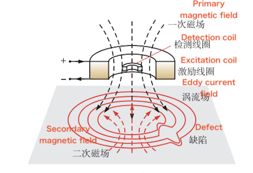
Figure 6. Schematic illustration of the eddy current testing principle
In addition to conventional ECT, several other eddy current testing techniques have been developed. Pulsed eddy current testing uses transient current pulses to generate time-varying magnetic fields that can penetrate protective or insulating layers, making it suitable for inspecting coated pipes and equipment. Eddy current array testing uses multiple sensors arranged to suit the geometry of the test specimen, enabling rapid and flexible inspection of large-area components. In remote-field eddy current testing, the receiving coil detects magnetic field signals that pass through the pipe wall and return to the interior, allowing the detection of inner- and outer-wall defects and wall-thickness variations. Motional eddy current testing is a relatively new technique that uses a DC coil or permanent magnet as the excitation source. Relative motion between the source and the conductive specimen generates eddy currents, making this technique suitable for high-speed inspection and potentially useful for real-time, in-line monitoring.
Owing to its non-contact nature, high sensitivity, and ability to inspect through multilayer tubular strings, eddy current testing (ECT) is an important technique for assessing the integrity of OCTG Pipes. Its main applications include corrosion detection, crack identification, and wall-thickness measurement. Pulsed eddy current (PEC) testing offers particular advantages in detecting corrosion in multilayer OCTG Pipe strings. Figure 7 shows the excitation and detection signals used in PEC inspection. To address the challenge of inspecting dual- or triple-string configurations, such as tubing and casing, PEC exploits the time-domain diffusion characteristics of the eddy current field to inspect the inner tubing and outer casing simultaneously. After the excitation current is switched off, the center of the eddy current field gradually shifts from the inner tubing toward the casing. This behavior supports quantitative defect assessment and helps identify whether a defect is located in the tubing or casing based on the signal timing. Eddy current array technology has also advanced to improve inspection efficiency and spatial resolution in the confined spaces encountered in downhole environments. By adjusting the excitation currents of multiple transmitting coils, the magnetic fields can be synthesized and focused, concentrating the eddy current field near the center of the array. Optimization algorithms based on the weighted least mean square error criterion can generate an optimal magnetic field distribution within power constraints, thereby improving the detection of localized defects. In addition, specialized inspection methods have been developed for specific applications and operating conditions of OCTG Pipes.
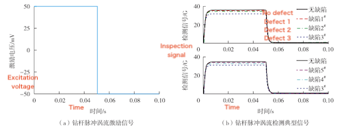
(a) Excitation signal for PEC inspection of drill pipe (b) Typical PEC detection signal for drill pipe
Figure 7. Excitation and detection signals for PEC inspection of OCTG Pipes
For ferromagnetic casings, rotating magnetic field eddy current sensors help overcome the limited penetration depth of conventional sensors in highly magnetic materials. Their sensitivity to small defects is evaluated by combining analytical models with dipole models of the defects. Threaded connections are particularly vulnerable because they are subjected to repeated tensile, torsional, and bending loads during drilling. To detect thread defects under these conditions, differential eddy current probes have been combined with signal processing algorithms based on morphological and energy features. This approach can accurately identify surface and subsurface thread defects despite interference caused by factors such as changes in inclination. To address the challenge of reconstructing wall thickness in multilayer tubular strings, researchers have developed a quantitative inversion method that combines time-window integration with Tikhonov regularization-based optimization. The method analyzes the relationship between integrated signals over specific time windows and wall thinning, using the time-domain characteristics of eddy current responses. Simulations of three-layer tubular strings showed that the method achieved an average relative error of less than 5.5% in estimating individual layer thicknesses.
Eddy current testing (ECT) offers significant advantages in inspecting multilayer OCTG Pipes and conducting high-speed, in-line inspection. In particular, pulsed eddy current (PEC) testing enables the inspection of multilayer tubular strings, addressing a limitation of conventional techniques. ECT is non-contact and highly sensitive to surface-breaking defects. The development of sensor arrays and the integration of different ECT techniques have further expanded its applications. However, the skin effect imposes an inherent limitation on penetration depth, making ECT less effective for detecting deep-seated defects. Although recent research has explored techniques such as magnetic field focusing and multifrequency excitation, the challenge of inspecting deeper regions remains unresolved.
Infrared thermography is based on the thermal conduction properties of materials, and its basic principle is illustrated in Figure 8. This technique offers several advantages: it is non-contact, enables the visualization of surface defects, and is sensitive to small temperature variations. Its underlying principle involves monitoring transient surface temperature changes caused by thermal diffusion after external excitation is applied to the test object. Various excitation methods have been developed for infrared thermography.
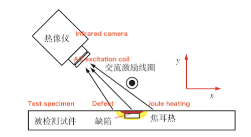
Figure 8. Schematic illustration of the infrared thermography principle
Pulsed excitation is one of the earliest methods developed for infrared thermography. It uses short-duration, high-energy pulses to generate transient thermal waves that propagate through the material by thermal diffusion. Its main advantages are rapid inspection, which is suitable for large-area scanning, and relatively simple equipment. However, pulsed excitation can produce non-uniform surface heating and has a relatively limited penetration depth. Lock-in excitation uses periodic sinusoidal modulation to generate steady-state thermal waves with controllable penetration depths. It offers a high signal-to-noise ratio and enables quantitative depth estimation through phase analysis, making it suitable for applications requiring precise measurements. Its main drawbacks are longer data acquisition times and sensitivity to environmental noise. Ultrasonic excitation uses mechanical vibrations to generate localized frictional heating at defect interfaces. It can detect defects that are difficult to identify using other methods, such as closed cracks and delamination, while providing high spatial resolution. However, it requires mechanical coupling and is primarily suitable for detecting defects in near-surface regions.
Infrared thermography is primarily used to detect surface and subsurface defects in OCTG Pipes, particularly those that affect heat conduction or diffusion, such as corrosion-induced wall thinning, surface cracks, and thread damage. As a non-contact inspection technique, it offers advantages in corrosion monitoring, leak detection, and thread defect assessment. Figure 9 shows thermal images of cracks. For the integrity assessment of drill pipe threaded connections, Chen et al. developed a scanning induction thermography system for detecting thread defects. To accommodate the complex thread geometry, the system uses induction heating to generate localized temperature differences at defect sites. An infrared camera captures the temperature field in real time, enabling sensitive detection of microcracks and fatigue damage on thread surfaces. To distinguish surface defects from subsurface defects in OCTG Pipes, Xu et al. proposed a scanning induction thermography method based on DC-biased magnetization. By controlling the magnetization direction and intensity, the method produces distinct eddy current loss distributions at defect locations, resulting in characteristic temperature patterns in the thermal images.
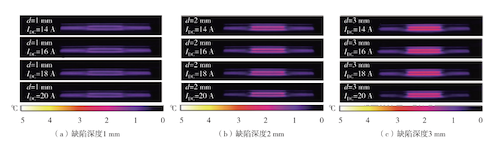
(a) Defect depth: 1 mm (b) Defect depth: 2 mm (c) Defect depth: 3 mm
Figure 9. Thermal images of cracks under different magnetization currents
Although infrared thermography for OCTG Pipe inspection remains at the engineering validation stage, its ability to visualize defects, operate without contact, and detect closed cracks demonstrates considerable potential. The intuitive thermal images also reduce the level of specialized expertise required for result interpretation. The development of excitation methods such as induction thermography and ultrasonic excitation has further expanded the available inspection approaches. However, environmental interference, high equipment costs, and difficulties in quantitative assessment remain major barriers to large-scale industrial application. Existing studies focus primarily on laboratory investigations and proof-of-concept demonstrations, with few documented field applications.
(1) The main failure modes of OCTG Pipes include chemical corrosion caused by CO₂, H₂S, and microorganisms, mechanical fatigue, and wear. Typical defects include uniform wall thinning, localized corrosion pits, surface and subsurface cracks, scratches, and dents. As different defect types exhibit distinct physical characteristics, inspection methods must be selected according to defect depth, orientation, and material continuity.
(2) Ultrasonic testing and magnetic flux leakage (MFL) testing are mature techniques widely used for wall-thickness monitoring and the detection of internal cracks and surface defects in OCTG Pipes. Eddy current testing is particularly suitable for inspecting multilayer tubular strings, while infrared thermography offers advantages in specialized applications, such as rapid imaging of surface microcracks.
(3) Electromagnetic testing is sensitive to surface and subsurface defects, whereas ultrasonic testing is better suited to detecting internal flaws. Combining ultrasonic and MFL techniques enables the simultaneous acquisition of wall-thickness and surface-defect data, while integrating eddy current testing with infrared thermography can improve microcrack detection. Future research should focus on multimodal inspection techniques that integrate complementary methods to achieve comprehensive detection of surface, subsurface, and internal defects.
(4) Artificial intelligence (AI), particularly deep learning, is increasingly being applied to nondestructive testing. Convolutional neural networks are used for defect recognition, while machine learning algorithms support feature extraction from inspection signals. Further research is needed on downhole online monitoring and the development and application of sensors capable of withstanding extreme operating conditions. In addition, AI-based diagnostic systems should be developed to cover the entire process, from defect detection and identification to quantification and grading, thereby supporting the full-lifecycle management of OCTG Pipes.