Posted Mar 31, 2022
Solutions to Valves Cavitation, Blockage and Noise
Production process automation is an important means to ensure efficiency and quality in large-scale industrial production. In the automation of the production process, the regulating valves used to control fluid flow have been widely used in the industrial automation systems of petroleum, chemical industry, power station, light industry, paper making, medicine, shipping, municipal administration and other industries. The regulating valve plays an important role in stabilizing production, optimizing control, maintenance and overhauling cost control. Therefore, how to select and applying the control valve well, so that the control valve can run at a high level is a key problem. This paper mainly analyzes and discusses the flash evaporation, cavitation, blocking prevention and noise of the control valve.
Flash evaporation and cavitation of regulating valves
Cavitation is a phenomenon of hydraulic flow. The direct cause of cavitation is the flash evaporation and cavitation of pipeline fluid due to the sudden change of resistance. When the fluid flows through the throttle of the regulating valve, the flow rate suddenly increases sharply. According to the law of conservation of fluid energy, the static pressure drops suddenly when the flow rate increases. When the outlet pressure reaches or is lower than the saturated vapor pressure of the fluid, part of the liquid is vaporized into gas, forming a small bubble of steam mixed with gas, and the gas-liquid coexistence phenomenon, which is the formation of flash evaporation. If the downstream pressure is higher than the saturated vapor pressure of the liquid, the bubble will quickly condense and burst under the action of high pressure, and an impact force will be formed at the moment of the bubble burst. This impact force will impact the valve core, valve seat and valve body, causing plastic deformation on their surfaces and forming rough honeycomb slag holes. This phenomenon is cavitation, which is the process of cavitation formation. Therefore, cavitation will lead to serious noise, vibration and material damage.
1.1 Selection
(1) Choose the valve with a small pressure recovery coefficient.
When the technological conditions permit, try to choose valves with small pressure recovery coefficients, such as ball valves and butterfly valves. If the process conditions must make the pressure difference △P >△PT (critical pressure difference for cavitation) of the regulating valves, two regulating valves can be used in series, so that the pressure difference △ p of each regulating valve is less than △ pt, and cavitation will not occur. If the pressure difference △P of the valve is less than 2.5MPa, cavitation will generally not occur, and even if cavitation occurs, it will not cause serious damage to the material.
(2) Choose angle regulating valve.
Because the medium in the angle valve directly flows to the center of the downstream pipeline inside the valve body, instead of directly hitting the wall, it can greatly reduce the number of saturated bubbles hitting the wall of the valve body, thus weakening the destructive power of flash evaporation.
1.2 Cavitation resistance of materials
From the direct result of cavitation, the damage is caused because the hardness of the material is not enough to resist the impact force released by bubble bursting. Therefore, from this point of view, we can consider using high-hardness materials. Generally, the commonly used method is surfacing or spray welding Stellar alloy on the stainless steel substrate to form a hardened surface at the fluid cavitation erosion. When the hardened surface is damaged, secondary surfacing or spray welding can be carried out, which can prolong the service life of the equipment and reduce the maintenance cost of enterprises.
1.3 Structure of regulating valve
Since cavitation is caused by the sudden change of pressure and the pressure drop required by the system cannot be reduced, a multi-stage valve core structure can be adopted, in which a big pressure change is decomposed several times. The valve core with this structure can divide the total pressure difference into several small pressure differences, and step by step reduce the pressure so that each stage does not exceed the critical pressure difference. Or the valve core and valve seat designed with special structures, such as labyrinth valve core and laminated valve core, etc., can make the pressure of every point of high-speed fluid when it passes through the valve core and valve seat be higher than the saturated vapor pressure at this temperature, or make the liquid collide with each other, resulting in high turbulence between channels so that the kinetic energy of the liquid becomes heat energy due to mutual friction, which can reduce the formation of bubbles.
1.4 Cavitation coefficient
Valves with different structures have different cavitation coefficients, and the calculation formula is as follows:
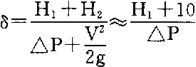
H1—— pressure m behind the valve (outlet);
H2—— the difference m between the saturated vapor pressure of atmospheric pressure and its temperature;
△ P—— pressure difference m before and after the valve.
Due to the different structures of various valves, the allowable cavitation coefficient δ is also different. If the calculated cavitation coefficient is greater than the allowable cavitation coefficient, it means that it is available and cavitation will not occur. If the allowable cavitation coefficient of the butterfly valve is 2.5, then:
When δ > 2.5, no cavitation will occur.
When 2.5 > δ > 1.5, slight cavitation will occur.
When δ < 1.5, vibration occurs.
When δ < 0.5 continues to be used, the valve and downstream piping will be damaged. The basic characteristic curve and operating characteristic curve of the valve can't be seen when cavitation occurs, let alone when the valve reaches the operating limit. It is clear from the above calculation. From the above calculation, it is not difficult to see that cavitation is closely related to the pressure H1 behind the valve. Increasing H1 will obviously change the situation.
The improvement method is:
1. Install the valve at the lower point of the pipeline.
2. Install an orifice plate on the pipeline behind the valve to increase resistance.
3. The valve outlet is open, and the water reservoir is directly used so that the space for bubble burst is increased and cavitation is reduced.
Blockage of regulating valves
When used in mud, paper pulp, pulp, caustic soda and other occasions, valve blockage is one of the common faults. In addition to the blockage caused by unclean medium, welding slag and scrap iron in the pipeline will also cause valve blockage. Therefore, the anti-blockage function of different valve types must be considered in the selection of regulating valves under these conditions. Generally, the following aspects should be considered:
(1) The smoother the flow path, the smoother the transition, the better;
(2) According to the calculation, if necessary, the valve seat diameter should be reduced to increase the throttling speed to improve the "self-cleaning" performance;
(3) Actuator with sufficient rigidity and thrust (torque);
(4) The angle stroke valve is far better than the straight stroke valve. The angle stroke valve overcomes the problems of the complicated flow path of the straight stroke valve and easy blockage caused by up-and-down guidance. When the medium flows through the angle stroke valve, it seems to flow in and out directly. The most typical one is the "O" ball valve, which has the best anti-blockage performance just like the straight pipe. Secondly, it is a full-function ultra-light valve, butterfly valve, etc.
The noise of regulating valves
The noise of regulating valve is the main pollution source in petrochemical production. To prevent the noise from regulating valves, three measures should be taken.
1. Noise generated by vibration
The noise generated by vibration generally comes from the vibration of the valve core. For example, when the spool moves horizontally in the sleeve, the gap between the spool and the sleeve can be as small as possible, or the sleeve with a hard surface can be used. Such as valve core or other components, which all have a natural vibration frequency. For this reason, the characteristics of the valve core can be changed by special casting or forging, and other types of valve cores can be replaced if necessary. For example, the noise caused by the pressure fluctuation of the fluid caused by the oscillatory displacement of the valve core is generally caused by the damping factors such as the actuator of the regulating circuit. For this reason, the damping coefficient can be readjusted or a damping facility can be added in the displacement direction of the valve core.
2. Aerodynamic sound caused by high-speed airflow.
At present, there are three ways to avoid aerodynamic noise. First of all, it is necessary to eliminate the noise source and limit the fluid speed through the regulating valve; Secondly, a valve body with a special structure is adopted, so that the fluid gradually decelerates through the tortuous flow path of the valve core and the valve seat; Third, the porous current limiting plate should be adopted, which absorbs part of the pressure drop behind the regulating valve, thus reducing the flow rate through the regulating valve, thus achieving the purpose of noise reduction.
3. Prevent hydrodynamic noise.
At the same time as cavitation, noise and vibration also appear. This kind of noise, also called hydrodynamic noise, how to avoid cavitation has been described earlier.
In a word, the selection of regulating valve should be adapted to local conditions, and it should be constantly summarized and innovated in the process of practice so that the adjusted parameters can be well controlled and the service life of regulating valve can be greatly increased.
Flash evaporation and cavitation of regulating valves
Cavitation is a phenomenon of hydraulic flow. The direct cause of cavitation is the flash evaporation and cavitation of pipeline fluid due to the sudden change of resistance. When the fluid flows through the throttle of the regulating valve, the flow rate suddenly increases sharply. According to the law of conservation of fluid energy, the static pressure drops suddenly when the flow rate increases. When the outlet pressure reaches or is lower than the saturated vapor pressure of the fluid, part of the liquid is vaporized into gas, forming a small bubble of steam mixed with gas, and the gas-liquid coexistence phenomenon, which is the formation of flash evaporation. If the downstream pressure is higher than the saturated vapor pressure of the liquid, the bubble will quickly condense and burst under the action of high pressure, and an impact force will be formed at the moment of the bubble burst. This impact force will impact the valve core, valve seat and valve body, causing plastic deformation on their surfaces and forming rough honeycomb slag holes. This phenomenon is cavitation, which is the process of cavitation formation. Therefore, cavitation will lead to serious noise, vibration and material damage.
1.1 Selection
(1) Choose the valve with a small pressure recovery coefficient.
When the technological conditions permit, try to choose valves with small pressure recovery coefficients, such as ball valves and butterfly valves. If the process conditions must make the pressure difference △P >△PT (critical pressure difference for cavitation) of the regulating valves, two regulating valves can be used in series, so that the pressure difference △ p of each regulating valve is less than △ pt, and cavitation will not occur. If the pressure difference △P of the valve is less than 2.5MPa, cavitation will generally not occur, and even if cavitation occurs, it will not cause serious damage to the material.
(2) Choose angle regulating valve.
Because the medium in the angle valve directly flows to the center of the downstream pipeline inside the valve body, instead of directly hitting the wall, it can greatly reduce the number of saturated bubbles hitting the wall of the valve body, thus weakening the destructive power of flash evaporation.
1.2 Cavitation resistance of materials
From the direct result of cavitation, the damage is caused because the hardness of the material is not enough to resist the impact force released by bubble bursting. Therefore, from this point of view, we can consider using high-hardness materials. Generally, the commonly used method is surfacing or spray welding Stellar alloy on the stainless steel substrate to form a hardened surface at the fluid cavitation erosion. When the hardened surface is damaged, secondary surfacing or spray welding can be carried out, which can prolong the service life of the equipment and reduce the maintenance cost of enterprises.
1.3 Structure of regulating valve
Since cavitation is caused by the sudden change of pressure and the pressure drop required by the system cannot be reduced, a multi-stage valve core structure can be adopted, in which a big pressure change is decomposed several times. The valve core with this structure can divide the total pressure difference into several small pressure differences, and step by step reduce the pressure so that each stage does not exceed the critical pressure difference. Or the valve core and valve seat designed with special structures, such as labyrinth valve core and laminated valve core, etc., can make the pressure of every point of high-speed fluid when it passes through the valve core and valve seat be higher than the saturated vapor pressure at this temperature, or make the liquid collide with each other, resulting in high turbulence between channels so that the kinetic energy of the liquid becomes heat energy due to mutual friction, which can reduce the formation of bubbles.
1.4 Cavitation coefficient
Valves with different structures have different cavitation coefficients, and the calculation formula is as follows:
H1—— pressure m behind the valve (outlet);
H2—— the difference m between the saturated vapor pressure of atmospheric pressure and its temperature;
△ P—— pressure difference m before and after the valve.
Due to the different structures of various valves, the allowable cavitation coefficient δ is also different. If the calculated cavitation coefficient is greater than the allowable cavitation coefficient, it means that it is available and cavitation will not occur. If the allowable cavitation coefficient of the butterfly valve is 2.5, then:
When δ > 2.5, no cavitation will occur.
When 2.5 > δ > 1.5, slight cavitation will occur.
When δ < 1.5, vibration occurs.
When δ < 0.5 continues to be used, the valve and downstream piping will be damaged. The basic characteristic curve and operating characteristic curve of the valve can't be seen when cavitation occurs, let alone when the valve reaches the operating limit. It is clear from the above calculation. From the above calculation, it is not difficult to see that cavitation is closely related to the pressure H1 behind the valve. Increasing H1 will obviously change the situation.
The improvement method is:
1. Install the valve at the lower point of the pipeline.
2. Install an orifice plate on the pipeline behind the valve to increase resistance.
3. The valve outlet is open, and the water reservoir is directly used so that the space for bubble burst is increased and cavitation is reduced.
Blockage of regulating valves
When used in mud, paper pulp, pulp, caustic soda and other occasions, valve blockage is one of the common faults. In addition to the blockage caused by unclean medium, welding slag and scrap iron in the pipeline will also cause valve blockage. Therefore, the anti-blockage function of different valve types must be considered in the selection of regulating valves under these conditions. Generally, the following aspects should be considered:
(1) The smoother the flow path, the smoother the transition, the better;
(2) According to the calculation, if necessary, the valve seat diameter should be reduced to increase the throttling speed to improve the "self-cleaning" performance;
(3) Actuator with sufficient rigidity and thrust (torque);
(4) The angle stroke valve is far better than the straight stroke valve. The angle stroke valve overcomes the problems of the complicated flow path of the straight stroke valve and easy blockage caused by up-and-down guidance. When the medium flows through the angle stroke valve, it seems to flow in and out directly. The most typical one is the "O" ball valve, which has the best anti-blockage performance just like the straight pipe. Secondly, it is a full-function ultra-light valve, butterfly valve, etc.
The noise of regulating valves
The noise of regulating valve is the main pollution source in petrochemical production. To prevent the noise from regulating valves, three measures should be taken.
1. Noise generated by vibration
The noise generated by vibration generally comes from the vibration of the valve core. For example, when the spool moves horizontally in the sleeve, the gap between the spool and the sleeve can be as small as possible, or the sleeve with a hard surface can be used. Such as valve core or other components, which all have a natural vibration frequency. For this reason, the characteristics of the valve core can be changed by special casting or forging, and other types of valve cores can be replaced if necessary. For example, the noise caused by the pressure fluctuation of the fluid caused by the oscillatory displacement of the valve core is generally caused by the damping factors such as the actuator of the regulating circuit. For this reason, the damping coefficient can be readjusted or a damping facility can be added in the displacement direction of the valve core.
2. Aerodynamic sound caused by high-speed airflow.
At present, there are three ways to avoid aerodynamic noise. First of all, it is necessary to eliminate the noise source and limit the fluid speed through the regulating valve; Secondly, a valve body with a special structure is adopted, so that the fluid gradually decelerates through the tortuous flow path of the valve core and the valve seat; Third, the porous current limiting plate should be adopted, which absorbs part of the pressure drop behind the regulating valve, thus reducing the flow rate through the regulating valve, thus achieving the purpose of noise reduction.
3. Prevent hydrodynamic noise.
At the same time as cavitation, noise and vibration also appear. This kind of noise, also called hydrodynamic noise, how to avoid cavitation has been described earlier.
In a word, the selection of regulating valve should be adapted to local conditions, and it should be constantly summarized and innovated in the process of practice so that the adjusted parameters can be well controlled and the service life of regulating valve can be greatly increased.
News
Industry News
Back to List
