Posted Nov 19, 2020
Bidirectional Sealing Floating Ball Valves for High Temperature and Viscous Media (Part One)
Abstract
This article introduces the processing characteristics of residual oil, heavy oil, wax oil and gasoline desulfurization in chemical plants. In view of the leakage problem in the use of a floating ball valve, the existing structure is analyzed, and a structural improvement plan is given. Also, the process control is described. At the same time, the selection of usability of valves for high-temperature viscous media are explained.
Overview
In the process of residual oil, heavy oil, wax oil and gasoline desulfurization, the medium has the characteristics of high temperature, high pressure, solid content and viscosity. The valves used in the device are all ball valves. After the device is used for a period of time, the system often has insufficient pressure, and the interlocking protection device alarms or stops. During troubleshooting, it was found that after a period of service, the floating ball valve used in the field was stuck and could not be effectively sealed, resulting in insufficient system charging and breakdowns. The failure of the ball valve restricts the stable, reliable, long-term operation and development of the system.
Failure analysis
No problem was found for the mounted ball valve used on site. The problem was the floating ball valve in the reverse pressure section. The ball valve has a one-way seal (Figure 1), and the direction of the disc spring is the high pressure end. When the mounted ball valve is working under positive pressure, there is no problem with the mounted ball valve. When the system has reverse pressure, the ball will be separated from the main valve seat, causing the medium to enter the gap between the ball and the valve seat and adhere to its surface. When the reverse pressure lasts longer, the effect becomes worse. When the positive pressure is restored again, the sealing surface of the ball and the valve seat is cushioned by the medium, and the valve seat and the ball cannot be effectively attached. Even if there is a sharp scraper, it cannot effectively clean the adhesives attached to the surface. This leads to problems such as leakage and ineffective close.
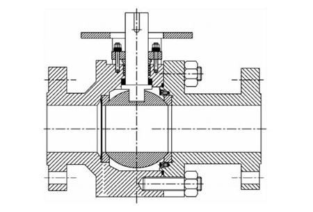
Figure 1 A floating ball valve with one-way sealing
Structure improvement
The other parts of the ball valve are not changed, only the valve seat structure is improved to make the valve seat symmetrical. The valve has no installation direction requirements and can be installed in any direction (Figure 2), which can effectively achieve two-way sealing.
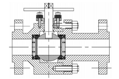
Figure 2 Two-way sealed floating ball valves
The spring is no longer a stud spring, but a disc spring. The stud spring needs too much protection, which makes the valve structure complicated, and the medium blockage can easily make the stud spring unable to move effectively. The design concept is to ensure that the medium can come in and go out. Therefore, the traditional dust-proof design alone cannot effectively prevent the accumulation of materials. Practice has proved that the use of an open structure can more effectively solve the problem of material accumulation. The flow of the medium itself and the valve opening and closing movement should be used to loosen and discharge the medium. The support ring is processed with a large arc surface, and the traditional right-angle and chamfered transition are not adopted. The impact of the medium is used for self-cleaning, which can loosen and wash away the materials accumulated in the slit during the opening and closing process. Similarly, the enlarged arc surface on the back of the valve seat is conducive to media discharge. The pin embedded in the support ring has a limiting effect and a pin structure is adopted, which occupies small space, reduces the accumulation of media and prevents jams during the rebound process. When there is reverse pressure in the system, the force of the entire valve seat is pressed on the pin instead of the graphite ring, which can prevent the graphite material from losing its elasticity and ensure that the sealing surface of the valve seat can rebound effectively. Use a sharp scraper for the valve seat to remove the deposits adhering to the sealing surface. See the Figure 3.
Figure 3 Structure of the valve seat
This article introduces the processing characteristics of residual oil, heavy oil, wax oil and gasoline desulfurization in chemical plants. In view of the leakage problem in the use of a floating ball valve, the existing structure is analyzed, and a structural improvement plan is given. Also, the process control is described. At the same time, the selection of usability of valves for high-temperature viscous media are explained.
Overview
In the process of residual oil, heavy oil, wax oil and gasoline desulfurization, the medium has the characteristics of high temperature, high pressure, solid content and viscosity. The valves used in the device are all ball valves. After the device is used for a period of time, the system often has insufficient pressure, and the interlocking protection device alarms or stops. During troubleshooting, it was found that after a period of service, the floating ball valve used in the field was stuck and could not be effectively sealed, resulting in insufficient system charging and breakdowns. The failure of the ball valve restricts the stable, reliable, long-term operation and development of the system.
Failure analysis
No problem was found for the mounted ball valve used on site. The problem was the floating ball valve in the reverse pressure section. The ball valve has a one-way seal (Figure 1), and the direction of the disc spring is the high pressure end. When the mounted ball valve is working under positive pressure, there is no problem with the mounted ball valve. When the system has reverse pressure, the ball will be separated from the main valve seat, causing the medium to enter the gap between the ball and the valve seat and adhere to its surface. When the reverse pressure lasts longer, the effect becomes worse. When the positive pressure is restored again, the sealing surface of the ball and the valve seat is cushioned by the medium, and the valve seat and the ball cannot be effectively attached. Even if there is a sharp scraper, it cannot effectively clean the adhesives attached to the surface. This leads to problems such as leakage and ineffective close.
Figure 1 A floating ball valve with one-way sealing
Structure improvement
The other parts of the ball valve are not changed, only the valve seat structure is improved to make the valve seat symmetrical. The valve has no installation direction requirements and can be installed in any direction (Figure 2), which can effectively achieve two-way sealing.
Figure 2 Two-way sealed floating ball valves
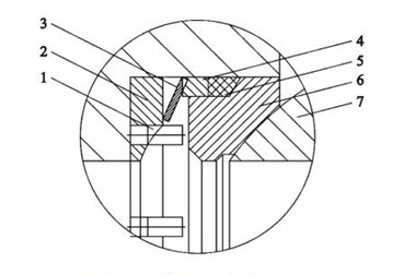
The spring is no longer a stud spring, but a disc spring. The stud spring needs too much protection, which makes the valve structure complicated, and the medium blockage can easily make the stud spring unable to move effectively. The design concept is to ensure that the medium can come in and go out. Therefore, the traditional dust-proof design alone cannot effectively prevent the accumulation of materials. Practice has proved that the use of an open structure can more effectively solve the problem of material accumulation. The flow of the medium itself and the valve opening and closing movement should be used to loosen and discharge the medium. The support ring is processed with a large arc surface, and the traditional right-angle and chamfered transition are not adopted. The impact of the medium is used for self-cleaning, which can loosen and wash away the materials accumulated in the slit during the opening and closing process. Similarly, the enlarged arc surface on the back of the valve seat is conducive to media discharge. The pin embedded in the support ring has a limiting effect and a pin structure is adopted, which occupies small space, reduces the accumulation of media and prevents jams during the rebound process. When there is reverse pressure in the system, the force of the entire valve seat is pressed on the pin instead of the graphite ring, which can prevent the graphite material from losing its elasticity and ensure that the sealing surface of the valve seat can rebound effectively. Use a sharp scraper for the valve seat to remove the deposits adhering to the sealing surface. See the Figure 3.
Figure 3 Structure of the valve seat
1. Pins 2. Support rings 3. Disc springs 4. Pressure rings 5. Graphite rings 6. Valve seats 7. Balls
The pin embedded in the support ring should be prevented from falling, and most of them adopt interference fit and spot welding. The disc spring rests on the support ring and the pressure ring to form a closed internal space, and it is difficult for impurities to enter. The graphite is deformed by the pre-tightening force of the disc spring to form an effective seal between the valve seat and the valve body.
Through structural changes, the floating ball valve is no longer the traditional valve with rear seals, but becomes the valve with front seals, and the torque will increase by two times. Therefore, when selecting the actuator, you need to ensure that the valve can be opened. At the same time, the torque will increase. The drive chain should also have sufficient strength to prevent deformation of connecting parts like the valve stem. In order to ensure the stability of the on-site load switch, the gap between the valve seat and the valve seat box should be controlled accurately and as small as possible to obtain a strong effect of scraping the medium. The valve seat head should have sufficient rigidity to prevent the valve seat from warping and jamming in the valve seat box.
