Check Valve Safety: Risks and Prevention
Check valves are essential components in industrial fluid systems, providing automatic protection against reverse flow without requiring external actuation. They are widely used in water supply networks, pump discharge lines, boiler systems, chemical processing plants, oil and gas facilities, power generation equipment, and compressed fluid systems. Although their construction is often relatively simple, their performance can have a significant impact on equipment protection, process stability, and operational safety.
The primary function of a check valve is to allow fluid to flow in the intended direction while restricting or preventing flow in the opposite direction. This function helps protect pumps from reverse rotation, reduce the risk of unwanted fluid transfer between connected systems, and maintain the intended operating conditions of pipelines and equipment. In systems with multiple pumps or parallel branches, check valves also help prevent operating equipment from discharging fluid backward through an idle unit.
However, installing a check valve does not automatically guarantee system safety. Its effectiveness depends on correct valve selection, appropriate sizing, suitable materials, proper installation, and effective maintenance. A poorly selected or improperly installed check valve may fail to close, create excessive pressure loss, generate damaging hydraulic transients, or allow unacceptable reverse leakage. In some applications, the valve itself can become a source of instability if its movement interacts unfavorably with changing flow conditions.
A comprehensive check valve safety strategy must therefore consider the entire lifecycle of the equipment, from engineering and procurement to commissioning, operation, inspection, and replacement. By identifying credible failure modes and applying appropriate preventive measures, industrial operators can improve system reliability, reduce maintenance costs, and minimize the consequences of reverse flow.
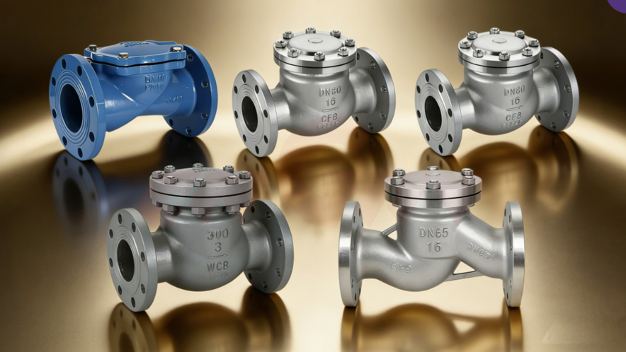
Reverse flow occurs when fluid moves against the intended direction of flow in a piping system. It may happen after a pump stops, when upstream pressure falls below downstream pressure, when another pump continues operating in a parallel system, or when pressure conditions change unexpectedly. Depending on the process, reverse flow can disrupt production, damage equipment, contaminate a fluid supply, or expose components to operating conditions for which they were not designed.
A check valve responds to the pressure and flow conditions around its closure element. When forward flow produces sufficient force to open the valve, the disc, ball, piston, or other closure component moves away from the seat. When forward flow decreases and reverse pressure develops, the closure element returns toward the seat, restricting reverse flow.
The exact response depends on the valve design, installation orientation, spring characteristics where applicable, fluid density, flow velocity, and pressure differential. Some check valves close primarily through gravity and reverse pressure, while others use springs or other mechanisms to encourage closure. Because different designs have different dynamic characteristics, selecting a valve based only on nominal pipe diameter can result in inadequate performance.
A check valve should also not automatically be treated as a positive isolation device. Some designs permit a degree of reverse leakage, particularly after wear or contamination. Where personnel safety, hazardous-fluid containment, or maintenance isolation requires dependable shutoff, an independently specified isolation arrangement may be necessary.
Pump discharge lines are among the most common applications for check valves. When a pump stops, the downstream fluid column may attempt to return through the pump. Depending on the system arrangement, reverse flow can cause the pump shaft and impeller to rotate backward, impose abnormal mechanical loads, and interfere with subsequent startup.
In parallel pump installations, check valves help prevent an operating pump from forcing fluid through a standby or stopped pump. Without appropriate protection, reverse flow may waste energy, create undesirable operating conditions, or damage mechanical components. The valve also helps preserve the intended division of flow between operating branches.
However, pump protection requires more than simply installing any check valve at the discharge. Engineers must consider the pump's operating curve, the pipeline profile, the fluid's inertia, and the speed at which the valve closes. A valve that closes too slowly may allow substantial reverse velocity to develop, while one that closes abruptly may produce a severe pressure transient.
The preferred design should be based on the dynamic behavior of the complete pumping system. Where reverse-flow consequences are significant, transient analysis and specialist valve selection can help identify the most appropriate closure characteristics.
Check valves can help maintain pressure separation between different sections of a fluid system. For example, they may prevent a higher-pressure branch from discharging backward into a lower-pressure line or reduce unwanted flow through inactive equipment. In this way, they support the intended operation of the network.
Nevertheless, a check valve does not independently regulate pressure or guarantee that a pipeline will remain free of pressure surges. Its closing action may actually contribute to a surge if reverse velocity has already developed. System pressure stability depends on the combined behavior of pumps, pipes, control valves, check valves, accumulators, surge vessels, and other components.
Engineers should therefore distinguish between preventing reverse flow and controlling hydraulic transients. A correctly selected check valve can contribute to system stability, but additional measures may be required when rapid flow changes, long pipelines, high velocities, or large elevation differences create significant transient risks.
Swing check valves use a disc that pivots away from the seat during forward flow and returns toward the seat when the flow decreases or reverses. Their relatively simple construction and generally low pressure drop make them common in water distribution, industrial process piping, and some pump discharge applications.
Their performance depends on disc travel, hinge design, orientation, and the velocity profile within the pipe. A swing check valve may perform poorly in applications with unstable flow, frequent reversals, or operating conditions that cause the disc to flutter. Excessive movement can accelerate wear at the hinge, pin, and seating surfaces.
Swing check valves may also close relatively slowly in certain systems. If reverse velocity develops before the disc reaches the seat, the closing action can generate a pressure surge. Engineers should therefore evaluate the expected flow-decay characteristics and transient conditions rather than assuming that a swing design is suitable for every pump installation.
Lift check valves use a closure element that moves approximately linearly away from the seat when forward pressure is sufficient. Depending on the design, the element may be guided within the valve body and returned to the seat by gravity, reverse pressure, or a spring.
These valves can provide useful sealing performance in appropriately selected applications, including certain high-pressure services. However, their operation can be sensitive to installation orientation, fluid properties, and the design of the internal guides. Some configurations create a greater pressure drop than other check valve types because the flow path changes direction or passes through a relatively restricted area.
Lift check valves should be selected according to the manufacturer's permitted installation position and operating envelope. The engineer must confirm that the fluid can move the closure element reliably and that the valve will not create unacceptable resistance, particularly in systems where pressure loss affects pump performance.
Dual-plate check valves use two spring-loaded plates that open under forward flow and return toward the closed position when the flow decreases. Their compact construction and relatively low weight make them attractive for applications where installation space is limited or where large-diameter piping makes heavier valve designs less convenient.
The spring-assisted closing action can help reduce the time required for closure, but actual performance depends on the design, flow conditions, spring characteristics, and reverse velocity. Incorrect sizing or unsuitable operating conditions may cause unstable plate movement, impact, wear, or inadequate sealing.
Wafer-style valves may be installed between flanges, which can simplify piping arrangements. However, the installation must follow the manufacturer's requirements for flow direction, flange dimensions, gasket selection, bolt tightening, and available clearance. Compact construction should not be confused with universal compatibility or superior safety.
Spring-assisted check valves are designed to encourage the closure element to return toward the seat as forward flow decreases. Some non-slam designs aim to achieve closure before significant reverse flow develops, thereby reducing the potential for pressure surges.
These characteristics can be valuable in pump discharge systems, high-velocity pipelines, and installations where transient loads are a major concern. Nevertheless, the term "non-slam" should not be interpreted as an absolute guarantee that no pressure surge can occur. The performance of the complete system depends on valve response, pump behavior, pipeline geometry, fluid properties, and operating conditions.
Selection should be based on documented dynamic performance, relevant application experience, and engineering analysis where necessary. A spring-assisted design may be less suitable if its cracking pressure creates excessive resistance or if the spring and closure mechanism are incompatible with the fluid, temperature, or required flow range.
| Valve type | Typical advantages | Important safety considerations |
|---|---|---|
| Swing check valve | Simple construction and relatively low pressure loss | Closing delay, disc movement, orientation, and potential water hammer |
| Lift check valve | Guided closure element and suitability for selected pressure services | Pressure drop, installation orientation, and internal sticking |
| Dual-plate check valve | Compact, lightweight design and spring-assisted closure | Plate stability, spring condition, and flange installation |
| Spring-loaded axial or nozzle check valve | Potentially rapid closure and reduced reverse-flow development | Correct sizing, cracking pressure, and documented dynamic performance |
| Ball check valve | Simple closure mechanism for certain fluids and piping arrangements | Ball sticking, deposits, orientation, and sealing compatibility |
The best choice depends on the actual application. Engineers should consider the intended function, fluid properties, pressure and temperature ratings, flow rate, pressure drop, closing behavior, maintenance requirements, and consequences of failure.
One of the most important check valve failure modes is the inability to close sufficiently when reverse pressure develops. Leakage may occur because of damaged seating surfaces, accumulated debris, corrosion, erosion, disc misalignment, a worn hinge, a damaged spring, or deposits that prevent the closure element from reaching the seat.
The consequences depend on the process. Reverse leakage in a simple water circulation line may cause inefficiency or unwanted flow, while leakage between incompatible chemical systems may cause contamination or an uncontrolled reaction. In high-pressure applications, reverse flow can also expose equipment to unexpected pressure or temperature conditions.
Operators should not assume that a check valve is functioning correctly merely because forward flow appears normal. Reverse leakage may remain unnoticed until an abnormal condition occurs. Appropriate inspection and functional testing should therefore be established according to the valve's criticality, service conditions, and applicable requirements.
Where reverse leakage presents a major hazard, engineers should evaluate whether a check valve alone provides sufficient protection. Depending on the system, additional isolation valves, monitored barriers, or other engineered safeguards may be required.
Water hammer is a transient pressure phenomenon caused by a rapid change in fluid velocity. In liquid systems, it can occur when a valve closes suddenly, a pump trips, or flow reverses. The resulting pressure wave travels through the pipeline and may produce loads that exceed those encountered during normal steady-state operation.
Check valves can contribute to water hammer if they close after reverse flow has accelerated. When the closure element finally strikes the seat, the abrupt deceleration of the moving fluid can create a pressure spike. The severity depends on factors such as pipe length, fluid velocity, wave speed, system elasticity, valve dynamics, and the timing of closure.
Potential consequences include pipe vibration, flange leakage, gasket damage, support failure, fatigue, and damage to connected equipment. Repeated pressure transients can shorten the service life of a system even when no single event immediately causes a visible failure.
Preventive measures may include selecting a valve with suitable dynamic characteristics, reducing excessive flow velocity, optimizing pump shutdown procedures, and evaluating surge-control devices. Where the consequences are significant, hydraulic transient analysis should be performed by competent engineers.
A check valve must move freely enough to respond to changes in flow and pressure. Internal deposits, scale, corrosion products, polymerized material, solid particles, and biological growth can interfere with the movement of the closure element. Mechanical damage, unsuitable clearances, or distorted components may also cause sticking.
Sticking can lead to different failure modes. A valve stuck closed may restrict forward flow, reduce system capacity, or create excessive pressure loss. A valve stuck open may permit reverse flow when the system requires closure. A valve that moves intermittently may generate unstable pressure behavior, noise, vibration, and accelerated component wear.
The risk is particularly important in systems handling viscous fluids, slurries, fluids containing suspended solids, or media that crystallize or polymerize. In these applications, internal geometry, material compatibility, and access for inspection or cleaning deserve special attention.
A suitable design should account for the actual fluid, expected contamination, operating temperature, and maintenance conditions. Routine inspection and cleaning should be planned where deposits or wear are foreseeable, and repeated sticking should trigger a review of the original valve selection.
Check valves are exposed to mechanical and chemical stresses that can gradually degrade their internal components. Corrosion may affect the body, closure element, hinge, spring, shaft, or seating surfaces, while erosion can occur when high-velocity fluid or abrasive particles repeatedly strike internal surfaces.
Material selection should reflect the medium's chemical composition, temperature, concentration, and operating conditions. Carbon steel may be appropriate for many services but can require corrosion management in wet or chemically aggressive environments. Stainless steel and specialized alloys can offer improved resistance in certain conditions, although no material is universally resistant to all fluids.
Elastomeric or polymeric seals also require careful selection. Temperature, chemical exposure, compression, aging, and repeated movement can alter their properties. The fact that a material is commonly used in industrial valves does not guarantee compatibility with every concentration or process temperature.
Manufacturers' compatibility data and application-specific engineering guidance should be used to confirm suitability. Where corrosion allowance, coatings, liners, or replaceable internal components are part of the design, their limitations and inspection requirements should be clearly documented.
The first step in check valve selection is to identify the fluid and its relevant properties. These may include density, viscosity, temperature, corrosivity, vapor pressure, suspended solids, lubricating characteristics, and tendency to deposit or crystallize. The fluid properties influence both material compatibility and the valve's dynamic response.
A valve that performs well with clean water may behave differently when handling viscous oil, abrasive slurry, steam, or a gas. Viscous fluids can increase resistance to movement and alter closure timing. Solids can obstruct the seat or guide mechanism, while corrosive media may damage components that are not directly visible during routine external inspection.
For hazardous media, engineers should also consider the consequences of reverse transfer, not only the mechanical integrity of the valve. If reverse flow could cause incompatible substances to mix, release toxic material, or create a fire hazard, the design may require additional protective measures beyond a conventional check valve.
Material compatibility should be confirmed for the complete wetted assembly, including the body, disc, shaft, spring, seat, and seals. Selecting a suitable body material while overlooking a vulnerable spring or sealing element can still result in premature failure.
Check valves must be rated for the maximum and minimum conditions they may encounter, including relevant transient conditions. The nominal pressure class or PN designation alone does not establish suitability at every temperature. Pressure-temperature limits depend on the valve design, material, applicable standard, and specific construction.
Engineers should identify the maximum allowable working pressure, operating temperature range, and relevant design conditions. They should also consider pressure surges, pump shutoff pressure, downstream backpressure, and potential exposure to higher pressure from connected equipment.
A valve installed in a system with a pressure rating greater than the valve's permitted rating may become a weak point in the pressure boundary. Failure can result in leakage, deformation, or rupture, depending on the severity of the mismatch. The entire assembly, including flanges, gaskets, bolting, and connecting pipework, must be compatible with the specified operating conditions.
Procurement specifications should state the applicable design standard and required pressure-temperature rating. Where a system has unusual operating conditions, the supplier should provide supporting technical data rather than relying on a generic product description.
Nominal pipe diameter is an important starting point, but it is not sufficient by itself to determine the correct check valve size. The valve must provide adequate flow capacity without creating excessive pressure loss or unstable operation. An oversized valve may fail to open sufficiently at low flow, causing the closure element to flutter or move repeatedly. An undersized valve may impose excessive resistance and reduce system performance.
Relevant selection parameters include normal and maximum flow rates, fluid properties, available pressure differential, piping configuration, and the valve's opening characteristics. Depending on the design, the manufacturer may provide flow coefficients, pressure-drop curves, minimum flow requirements, or other data useful for sizing.
In pump systems, the valve should be assessed against the pump curve and expected operating range. The selected valve must open reliably at the available forward differential pressure and close appropriately when flow decreases. These requirements should be evaluated for startup, steady operation, shutdown, and credible abnormal conditions.
Correct sizing helps balance energy efficiency, mechanical stability, and reverse-flow protection. It also reduces the likelihood that a valve will operate outside the range for which it was designed.
Check valves are directional devices, and their installation must follow the flow arrow or other identification provided by the manufacturer. Installing a valve backward can prevent normal forward flow or defeat the intended function. Incorrect orientation may also affect gravity-assisted closure, spring performance, or the stability of the internal closure element.
Before installation, personnel should confirm the valve model, flow direction, installation position, pressure rating, and compatibility with the piping layout. The body marking and technical documentation should be checked rather than relying on visual assumptions, because different valve designs may look similar while having different operating requirements.
The permitted orientation varies by design. Some valves are intended for horizontal pipelines, some can be installed vertically with upward flow, and others have additional restrictions. Gravity-dependent designs may not function correctly if installed in an orientation that prevents the closure element from returning to the seat as intended.
Installation instructions should be included in the work package, and the final arrangement should be checked before commissioning. This simple control can prevent avoidable operational problems and reduce the risk of commissioning an ineffective safety component.
Piping configuration can influence the flow profile entering and leaving a check valve. Nearby elbows, reducers, tees, pumps, and other fittings may create swirl or uneven velocity distribution. Depending on the valve design, these conditions can contribute to unstable movement, vibration, noise, or accelerated wear.
Manufacturers may specify straight-pipe requirements or restrictions on installation near certain fittings. Such recommendations should be followed where applicable. The valve should also be installed with adequate access for inspection, removal, and maintenance, especially when it is located in a critical service line.
Mechanical loads from the piping system should not be transferred unintentionally to the valve body. Poor alignment, excessive flange loading, or unsupported pipework can introduce stresses that distort the valve or compromise connections. Installation should therefore include appropriate pipe supports, alignment checks, gasket selection, and controlled bolt tightening.
The installation design should consider not only whether the valve physically fits into the pipeline but also whether it can operate and be maintained safely throughout its intended service life.
A check valve is not a substitute for all other forms of system protection. Isolation valves may be needed to permit maintenance, while drains and vents may be necessary for safe removal or inspection. The arrangement must be designed so that maintenance can be carried out without exposing personnel to trapped pressure or hazardous fluid.
In systems susceptible to water hammer, additional measures may be necessary. These may include surge vessels, air chambers designed for the application, pressure-relief arrangements, controlled pump shutdown, or other transient-control devices. The appropriate solution depends on the hydraulic characteristics of the system and should be selected through engineering analysis.
Care is also required when adding isolation valves around a check valve. The arrangement must not unintentionally trap liquid in a section where thermal expansion could create dangerous pressure. Any maintenance configuration should be reviewed for credible pressure sources and safe depressurization methods.
A well-designed installation treats the check valve as one component within a complete protective system rather than expecting it to resolve every flow-control and pressure-management problem.
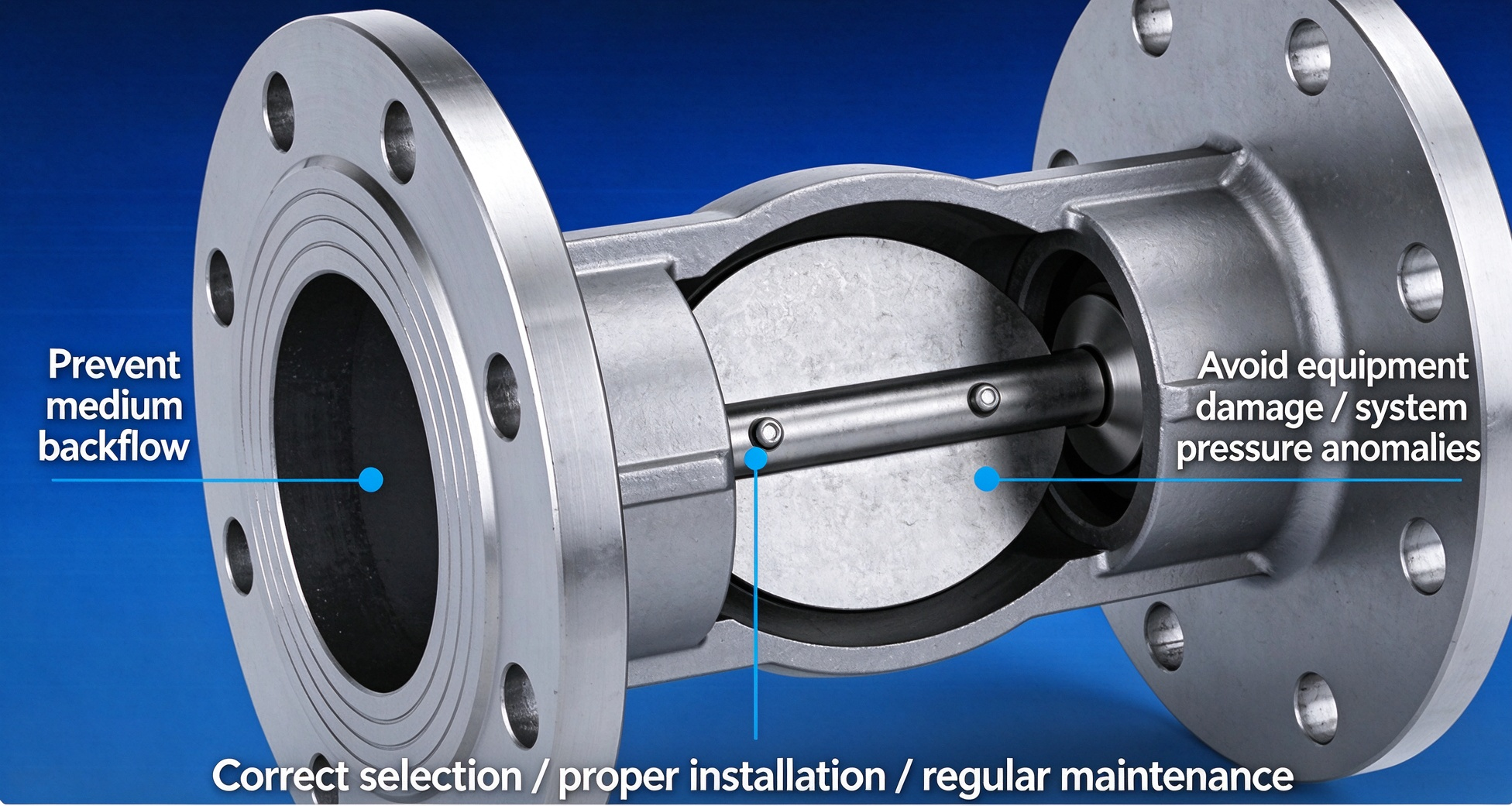
Check valve maintenance should reflect the valve's service conditions, operating history, and consequences of failure. A valve in clean water service with stable operating conditions may require a different inspection frequency from one handling corrosive chemicals, abrasive slurry, or high-pressure steam. Criticality should be considered when establishing the maintenance plan.
A risk-based program should identify the valve's function, credible failure modes, available detection methods, and the consequences of malfunction. It should also account for the difficulty of access, availability of spare parts, and the time required to isolate the affected equipment.
Inspection activities may include external leakage checks, observation of abnormal noise or vibration, review of pressure and flow trends, and examination of the valve during planned shutdowns. Internal inspection may be appropriate where deposits, corrosion, or wear are likely to affect operation.
Inspection intervals should not be chosen arbitrarily. They should be informed by manufacturer guidance, applicable regulations, historical performance, process severity, and the facility's maintenance strategy. When a valve is safety-critical, the inspection program should explicitly address how its required function will be verified.
During an appropriate maintenance opportunity, internal inspection can reveal damage that cannot be identified externally. Depending on the design, inspectors may examine the disc, ball, hinge pin, spring, guide surfaces, seat, and body cavity for corrosion, erosion, cracking, deposits, and abnormal wear.
Seating surfaces deserve particular attention because small defects can reduce shutoff performance. Scratches, embedded particles, deformation, and uneven contact may allow reverse leakage. Moving components should also be checked for excessive clearance, binding, or wear that could delay closure.
The inspection method must suit the valve design and service. Some valves can be disassembled for repair, while others may require specialized procedures or replacement. Before opening a valve, the system must be safely isolated, depressurized, drained, and verified free of hazardous energy according to the facility's procedures.
Any damaged components should be evaluated against the manufacturer's repair criteria and applicable engineering requirements. Reassembly should follow the approved procedure, including replacement of required seals and verification that all components are correctly positioned.
Cleaning may restore proper movement when deposits or contamination are responsible for sticking. However, the cleaning method must be compatible with the body material, internal components, and process medium. Aggressive mechanical cleaning or unsuitable chemicals can damage seats, coatings, seals, and precision surfaces.
Where components are worn or corroded beyond acceptable limits, replacement may be safer and more economical than repeated repair. Spare parts should match the approved valve model and material specification. Substituting an apparently similar spring, seal, disc, or fastener can alter the valve's opening characteristics or compromise its pressure rating.
After maintenance, the valve should be reassembled and tested according to the required procedure. Depending on the application, verification may include functional checks, leakage testing, and inspection of associated connections. The maintenance record should identify the work performed, replaced components, inspection findings, and any restrictions on returning the equipment to service.
Although many check valves operate automatically and do not provide a direct position signal, changes in system behavior can indicate developing problems. Abnormal noise, repeated impact, excessive vibration, unexpected pressure fluctuations, or changes in flow may suggest that the valve is not operating as intended.
For example, repeated disc impact may indicate unsuitable closure characteristics or unstable flow. A higher-than-expected pressure drop may suggest restricted movement, internal deposits, or incorrect sizing. Reverse flow after pump shutdown may indicate leakage, delayed closure, a damaged seating surface, or a broader system problem.
These symptoms are not definitive diagnoses. Similar effects may arise from pump issues, air entrainment, pipeline support problems, or other components. Investigation should therefore consider the complete system rather than replacing the check valve automatically whenever abnormal behavior occurs.
In critical applications, appropriate instrumentation can improve fault detection. Pressure sensors, flow measurement, vibration monitoring, and pump status data may help engineers identify operating patterns that warrant inspection. Monitoring should be selected according to the actual risk and value of the information, rather than installed indiscriminately on every valve.
Check valve testing should verify the function that the valve is required to perform. A visual inspection alone cannot establish that the closure element will respond correctly under all operating conditions. Depending on the valve design and service, testing may include checking forward opening, reverse closure, seat leakage, mechanical movement, or other manufacturer-defined performance characteristics.
The test procedure should specify the test medium, pressure differential, flow conditions, acceptance criteria, and safety precautions. Testing must follow the applicable code, product standard, and manufacturer requirements. A test performed under one condition should not be interpreted as proof of satisfactory operation under every pressure, temperature, and flow regime.
For valves in hazardous service, the testing method must also consider personnel exposure and the risk of releasing process media. If the valve must be removed for testing, the system isolation and depressurization procedure should be carefully planned. If in-situ testing is used, the method must provide meaningful evidence of the required function.
Test results should be documented and compared with previous findings where possible. Trends in leakage, response, or mechanical condition can support better maintenance decisions and help identify recurring failure modes.
Inspection and testing records are essential for understanding long-term valve performance. Records should identify the valve, its location, service conditions, inspection date, test method, findings, repairs, and replacement components. For critical valves, the documentation should also identify the person or organization responsible for the work and any outstanding corrective actions.
Accurate records allow maintenance teams to distinguish isolated failures from recurring problems. If several valves of the same model experience similar sticking or leakage, the facility may need to review the original selection, fluid conditions, or installation arrangement. If failures occur only after certain operating events, the system may require a transient or process review.
A digital maintenance system can help organize records, schedule inspections, and link valve data to drawings and equipment registers. However, digital records are useful only when they are complete, accurate, and kept current. Documentation should support engineering decisions rather than become a routine administrative task disconnected from field conditions.
Chemical and petrochemical plants may use check valves to prevent reverse flow between process units, pumps, storage systems, and utility lines. The risks can be significant when the connected fluids are toxic, flammable, corrosive, or chemically incompatible. Reverse transfer may cause contamination, unwanted reactions, overpressure, or loss of containment.
Selection should account for the chemical compatibility of all wetted materials and the expected pressure and temperature range. Engineers should consider whether the fluid can polymerize, crystallize, deposit solids, or corrode internal components. The valve's ability to close reliably under actual process conditions must be evaluated against the consequences of failure.
Where a check valve forms part of a broader process safety strategy, it should be treated according to its defined function and criticality. It should not automatically be credited as a fully reliable isolation barrier without evidence that its leakage characteristics and failure modes meet the required safety objective.
Depending on the process hazard analysis, additional isolation, monitoring, or protective layers may be required. Maintenance and testing arrangements should ensure that the valve's required function can be verified without creating unacceptable exposure to hazardous substances.
In boiler and steam-related piping, check valves may help control flow direction and prevent reverse flow under specified conditions. However, high temperature, pressure, thermal cycling, condensate, and rapid changes in operating conditions create additional challenges. Valve materials, pressure-temperature ratings, closure behavior, and associated piping must be suitable for the actual service.
The role of a check valve in a boiler system depends on the exact piping arrangement and applicable code requirements. It should not be assumed that a conventional check valve alone can prevent overpressure or replace required pressure-relief devices, safety controls, or other protective equipment.
Thermal expansion and trapped condensate can create additional risks. Incorrect installation or unsuitable operating procedures may contribute to water hammer, while corrosion and erosion can degrade internal surfaces over time. Engineering review should consider startup, shutdown, low-flow operation, and other transient conditions rather than focusing only on steady-state operation.
Inspection and maintenance should follow the applicable regulatory framework and manufacturer instructions. Any modification to a safety-related steam or boiler installation should be reviewed by competent personnel before implementation.
Municipal and industrial water systems use check valves to protect pumps, manage branch flow, and reduce the risk of reverse movement through connected equipment. Wastewater systems may also contain suspended solids, fibers, grease, and other contaminants that can obstruct internal mechanisms or interfere with seating.
The selected design should suit the fluid quality, installation orientation, operating frequency, and available maintenance access. Valves installed in remote chambers or underground locations may be difficult to inspect, making appropriate design selection and maintenance planning particularly important.
Pressure transients can be significant in long pipelines or systems with large elevation changes. Pump trips and rapid closure may generate surges that exceed normal operating pressure. Engineers should assess the hydraulic profile and transient behavior where the potential consequences justify it.
For potable water applications, material suitability and applicable sanitary requirements must also be considered. In wastewater systems, access for cleaning and removal of trapped debris may be a major selection criterion. Reliability improves when the valve is chosen for the real service environment rather than merely matched to the nominal pipe diameter.
Check valves in oil, gas, and compressed fluid systems may be exposed to high pressure, variable flow, gas compressibility, vibration, and potentially hazardous releases. Their behavior can differ substantially from that of valves used in low-pressure liquid systems. Gas systems may also present different transient and leakage characteristics because compressibility affects pressure-wave behavior and stored energy.
Engineers should verify the design pressure, temperature range, material compatibility, relevant industry standards, and required leakage performance. Where reverse flow could create a hazardous condition, the check valve's suitability should be supported by application-specific evidence and the overall protection design.
The consequences of failure should guide the level of verification, documentation, and maintenance. For critical services, material traceability, inspection records, and defined testing requirements may be necessary. Installation should also consider vibration, support loads, and accessibility for inspection.
A check valve should not be used as the sole safeguard against every possible hazardous flow scenario. The complete system may require additional isolation, pressure protection, detection, or shutdown measures according to the relevant engineering and regulatory requirements.
The first step in lifecycle management is to define what the check valve must accomplish and what could happen if it fails. The required function may be as simple as preventing reverse flow through a standby pump, or it may involve preventing hazardous cross-contamination between process systems.
Engineers should document the normal and abnormal operating conditions, fluid properties, expected flow range, pressure and temperature limits, and consequences of reverse flow. They should also identify whether the valve is expected to provide routine process protection, contribute to a safety-related function, or operate under specialized regulatory requirements.
This definition establishes the basis for selection, installation, inspection, and testing. Without it, maintenance teams may focus on general condition while overlooking the specific function that makes the valve important to the system.
During procurement, the valve should be selected according to the required duty rather than the lowest price or most familiar design. The specification should define the valve type, size, material, pressure rating, temperature range, end connections, installation restrictions, and relevant performance requirements.
Where closure dynamics are important, the supplier should provide appropriate technical information. For hazardous or high-consequence service, the purchaser may also specify material documentation, inspection records, functional testing, and other verification requirements. These requirements should be agreed before the order is placed.
Supplier evaluation should include technical capability, manufacturing quality, traceability, service support, and spare-parts availability. A low-cost valve may be suitable for a low-risk application, but a critical installation requires evidence that the proposed product meets the relevant engineering requirements.
Installation quality should be verified against the approved drawings and manufacturer instructions. Checks should include flow direction, orientation, flange alignment, gasket compatibility, support arrangements, and access for future maintenance. The piping system should be inspected for debris that could damage the valve or prevent the closure element from seating properly.
Commissioning should verify that the valve performs its intended function under the specified test conditions. Depending on the system, this may include observing forward flow, checking pressure behavior during shutdown, verifying associated instrumentation, and confirming that the valve does not create unacceptable noise or vibration.
Any abnormal behavior should be investigated before the system is accepted for routine service. Commissioning records provide a baseline for later maintenance and help distinguish original installation problems from deterioration that develops during operation.
During operation, the facility should follow an inspection and maintenance plan based on service severity and failure consequences. Relevant observations may include leakage, pressure drop, vibration, abnormal noise, operating changes, and the condition of associated pumps or piping.
Maintenance findings should be used to update the risk assessment and inspection schedule. If the valve repeatedly sticks, leaks, or causes pressure surges, simply increasing inspection frequency may not solve the underlying problem. The correct response may require resizing, changing the valve design, revising operating procedures, or modifying the piping system.
Lifecycle management is a continuous process. Operational experience should inform future procurement, engineering standards, and maintenance planning. This feedback loop helps organizations reduce recurring failures and improve the reliability of similar installations throughout the facility.
Before purchasing, installing, or maintaining a check valve, engineering and maintenance teams can use the following checklist to identify common areas of risk.
Design and selection
- Confirm the required reverse-flow protection function.
- Verify the fluid composition, viscosity, temperature, and contamination level.
- Check pressure-temperature ratings and applicable design standards.
- Confirm the valve size and flow capacity.
- Assess closure dynamics and potential water hammer.
- Verify material compatibility and required leakage performance.
Installation and commissioning
- Confirm the correct flow direction and permitted orientation.
- Check flange alignment, gasket suitability, and bolting.
- Verify piping supports and maintenance access.
- Remove debris and contamination before commissioning.
- Confirm that associated isolation and surge-control arrangements are suitable.
- Document commissioning results and abnormal observations.
Operation and maintenance
- Establish inspection intervals based on risk and service conditions.
- Monitor abnormal noise, vibration, pressure fluctuations, and leakage.
- Inspect internal components when required and safe to do so.
- Replace worn or damaged parts with approved components.
- Verify functional performance after maintenance.
- Keep accurate inspection, repair, and testing records.
Lifecycle review
- Investigate repeated failures and identify root causes.
- Review whether the valve remains suitable for actual operating conditions.
- Confirm the availability of spare parts and technical support.
- Update specifications based on field experience.
- Reassess additional protection where reverse flow has serious consequences.
This checklist should be adapted to the applicable code, facility procedures, manufacturer instructions, and the specific risks of the installation. It is a practical aid, not a substitute for engineering review or mandatory inspection requirements.
Check valves play a fundamental role in preventing reverse flow, protecting equipment, and supporting the stable operation of industrial fluid systems. Their importance extends across water infrastructure, chemical processing, power generation, oil and gas, and many other applications. However, their safety value depends on more than the presence of a valve in the pipeline. Incorrect selection, poor installation, unsuitable materials, dynamic instability, and inadequate maintenance can all undermine the intended protection.
A dependable strategy begins with defining the required function and selecting a valve that matches the actual fluid properties, pressure, temperature, flow range, and operating conditions. Installation must follow the manufacturer's requirements, and the surrounding piping system must be designed to manage pressure transients and provide safe maintenance access. Inspection, functional testing, and accurate records help verify that the valve continues to perform its intended role.
Most importantly, check valve safety should be managed throughout the equipment lifecycle. When manufacturers, engineers, operators, and maintenance teams work together to identify failure modes, investigate recurring problems, and improve specifications, check valves become more dependable components within a broader safety system. This systematic approach helps protect equipment, reduce unplanned downtime, and support safer, more reliable industrial operations.
