Development of a Pre-welding Seam Tracking System for Spiral Steel Pipe Welding
Abstract: To address poor seam tracking accuracy and excessive manual intervention during submerged arc pre-welding of spiral steel pipes, a real-time seam tracking system was developed by integrating vision sensing and adaptive control technologies. The system significantly improves the accuracy and stability of seam tracking in pre-welding units, reduces seam deviation and welding defects, and improves both welding quality and production efficiency.
Steel pipes are widely used in industries such as oil and gas, chemicals, power generation, including nuclear power, machinery manufacturing, automotive, shipbuilding, and aerospace. As a critical steel product, they support major national engineering projects and the manufacture of key equipment. As essential materials for transportation and structural applications, spiral steel pipes are subject to increasingly demanding requirements for production quality and efficiency.
Pre-welding is a key process in spiral steel pipe manufacturing, and its quality directly affects the pipe's mechanical properties, sealing integrity, and service life. However, during continuous high-speed production, the dynamic forming characteristics of spiral steel pipes, including variations in pipe diameter, strip misalignment, and complex spatial trajectories of the weld seam, present significant challenges to welding precision.
Traditional manual monitoring relies heavily on operator experience and is characterized by slow response and limited resistance to interference. Consequently, it cannot meet the requirements for high-precision and highly reliable welding. This can lead to defects such as seam misalignment and incomplete fusion, which in turn reduce production efficiency and the pass rate of finished products.
As a core component of the automated control system for spiral pipe pre-welding, the seam tracking system plays a key role in overcoming these technical challenges. By integrating high-precision sensing technology, real-time data processing algorithms, and adaptive control strategies, the system can dynamically detect weld seam position deviations and adjust the welding torch trajectory in real time, ensuring that the welding process closely follows the preset path. Therefore, in-depth research into seam tracking systems and their broader application in spiral pipe pre-welding control systems is of great significance for promoting the high-quality development of the spiral pipe manufacturing industry.
The seam tracking system consists of two main components:
- META tracking system
- Welding head slide control system
The META tracking system includes the following components:
- Laser tracking sensor
- Main tracking controller
- Industrial PC for tracking signal processing
- Siemens S7-1500 PLC
- Touchscreen display
During operation, the laser tracking sensor captures images of the weld seam and transmits the acquired analog signals to the S7-1500 PLC for analog-to-digital conversion and analysis. Based on the tracking mode and parameters preset on the touchscreen, the system performs calculations using specific algorithms. The resulting control commands are then transmitted through the PLC to the pre-welding control system. The control system drives the slide mechanism to adjust the position of the welding torch, thereby achieving automatic seam tracking.
The laser seam tracking sensor shown in Figure 1 operates based on the principle of laser triangulation. A laser beam is expanded into a line and projected onto the workpiece surface to detect the position and height of the weld seam. The sensor head is equipped with a camera and two laser sources. The lasers project a line onto the workpiece surface beneath the sensor head. The laser beam strikes the surface at a variable angle and is then reflected back toward the sensor. An optical filter installed in front of the camera allows the laser light to pass through while blocking welding arc light and other sources of interference, enabling the camera to capture the laser line clearly.
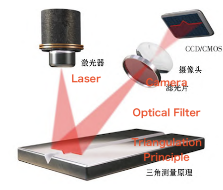
Figure 1. Laser Weld Seam Sensor
The META tracking and monitoring principle is illustrated in Figure 2. As shown, when the workpiece is very close to the sensor, the laser tracking sensor adjusts the angle of the laser beam, causing the laser spot to shift forward on the workpiece. Conversely, adjusting the beam angle in the opposite direction causes the laser spot to shift backward. The camera directly captures the laser line, allowing the system to measure the distance between the laser sensor and the workpiece surface beneath it. By analyzing the shape of the red laser line on the workpiece, the system can determine the surface profile and weld seam location. This enables the sensor head to accurately measure the position of the weld seam relative to the workpiece edges.
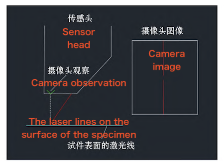
Figure 2. META Tracking and Monitoring Principle
The main controller of the laser tracking sensor is connected to an industrial computer via the PROFINET communication protocol. The PLC controller first reads the signal status at the input terminals and stores the corresponding data in registers. It then transmits the acquired analog signals to the industrial computer, where they are converted into digital signals for further processing.
Operators can configure tracking parameters, including weld seam type, weld seam width, and tracking mode, through the tracking software interface on the industrial computer's touchscreen. Based on the configured parameters and standard algorithms, the tracking system processes the acquired weld seam data and generates control signals, which are then transmitted to the PLC system. The PLC converts these signals into ±10 V analog outputs and sends them to the pre-welding control system to drive the tracking slide.
The internal and external welding torches of the pre-welding unit are mounted on dedicated 3D drive slides for internal and external welding, respectively. The torches track the steel pipe weld seam in real time by moving with the corresponding slides. Each drive slide consists of a vertical slide and a longitudinal slide, which control the torch height and longitudinal position to maintain accurate weld seam tracking. The slides are driven by Siemens S120 servo motors. The torch drive slide assembly is shown in Figure 3.
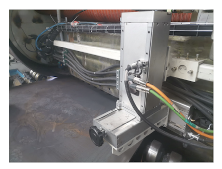
Figure 3. Torch Slide Assembly
The welding control system of the pre-welding unit is built around a Siemens S7-1500 PLC, an S120 servo controller, and an Advantech UNO-2484G industrial computer. The PLC processes and calculates the control signals received from the tracking system and then drives the welding torch assembly through the S120 servo motors. Because the tracking sensor is mounted close to the welding torch and moves together with it, any deviation detected by the sensor directly reflects the actual positional deviation of the welding torch.
During welding, the system supports both manual and automatic seam tracking modes, allowing operators to switch seamlessly between them. In manual mode, the operator uses a joystick to adjust the height and longitudinal position of the welding torch and manually track the weld seam. The movement speed is set to a preset value entered in the input field of the WinCC interface on the industrial PC.
In automatic tracking mode, the welding torch slide is fully controlled by the laser tracking system, which automatically adjusts the torch position and height to follow the weld seam. However, when the pipe forming quality is poor or the weld groove geometry is irregular, the automatic tracking system may fail to accurately identify the weld seam. In such cases, the operator must switch to manual control.
Because the welding torch and laser tracking sensor are mounted on the same slide, manual intervention changes the positions of the tracking teach points. To resume automatic tracking, the teach points must be redefined in the tracking software. When the system is switched back to automatic mode, tracking resumes from the newly defined teach points. The internal and external welding torches are shown in Figure 4.
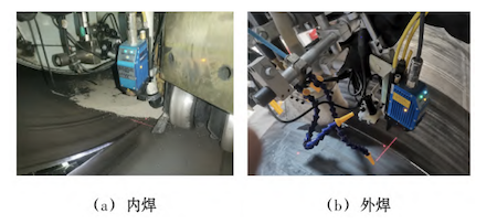
Figure 4. Internal and External Welding Torches
During welding, the laser tracking sensor and welding torch are mounted on the same slide and move together. Since spiral pipe pre-welding involves simultaneous internal and external welding, with the internal torch tracking the inner groove and the external torch tracking the outer groove, seam tracking becomes challenging when producing small-diameter, thin-walled pipes. Owing to the thinness of the raw steel plate, it is difficult to maintain consistent inner and outer groove profiles during forming and edge milling. Significant variations in groove geometry can adversely affect pre-weld seam tracking and welding quality.
To address this issue, a servo motor works in conjunction with the tracking system to adjust the tracking depth, thereby enabling continuous seam tracking and welding. The laser tracking sensor mounted on the tracking slide detects both the internal and external seams and transmits the tracking signals to the welding control system. The control system processes these signals and sends commands to control the movement of the tracking slide. The slide then moves the sensor accordingly, ensuring accurate seam tracking and positioning. An encoder is mounted on the servo motor that drives the vertical and longitudinal tracking slide assembly to detect and analyze positional deviation signals, ensuring that the welding torch accurately tracks the seam.
Under normal forming and edge-milling conditions, the weld tracking system guides the internal and external welding slides for vertical tracking. However, when producing certain types of steel pipes, such as thin-walled pipes, less-than-ideal forming or edge-milling conditions are sometimes unavoidable, resulting in unstable tracking or deviations from the weld seam. Therefore, additional sensors are required to further improve tracking accuracy.
To address this issue, a height sensor (SICK height-detection sensor) is installed on the vertical tracking slide of the welding torch to measure the distance between the torch and the steel pipe surface. The sensor converts the measured distance into a 4–20 mA analog signal and transmits it to the analog input module (6ES7531-7KF00-0AB0) of the S7-1500 PLC in the pre-welding control system. The analog input module converts the 4–20 mA signal into a digital value in the range of 0–27,648. After digital filtering and processing, the actual height of the welding torch is determined. This value is then compared with the tracking parameters configured in the WinCC interface on the industrial PC. The Siemens S7-1500 PID function block is used to implement proportional-integral (PI) control, enabling automatic vertical tracking of the welding torch.
Laser tracking for internal and external welding enables real-time, precise detection of the seam position and dynamic adjustment of the torch trajectory. This significantly reduces the need for manual intervention, improves welding accuracy and consistency, and helps eliminate weld defects caused by human error. The system responds rapidly to changes in seam position, enabling continuous operation without the frequent positional adjustments required during manual welding and thereby shortening the welding cycle.
However, current automatic tracking technologies have limitations under complex operating conditions, such as imperfect steel pipe forming, irregular and unpredictable weld seams and bevels, and composite welding involving materials with substantially different properties. Consequently, the forming quality of spiral steel pipes remains a critical factor in achieving reliable automatic seam tracking and improving weld quality during pre-welding.
The spiral steel pipe pre-welding unit is currently in operation at Shandong Qufu Donghong Pipe Industry Co., Ltd., with its application scenarios shown in Figures 5 and 6. The unit incorporates a real-time seam tracking system based on visual sensing and adaptive control, which improves tracking accuracy and stability. The system reduces weld deviations and welding defects and achieves a 99.8% flaw detection pass rate, thereby improving welding quality and production efficiency.
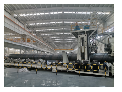
Figure 5. Spiral steel pipe pre-welding unit
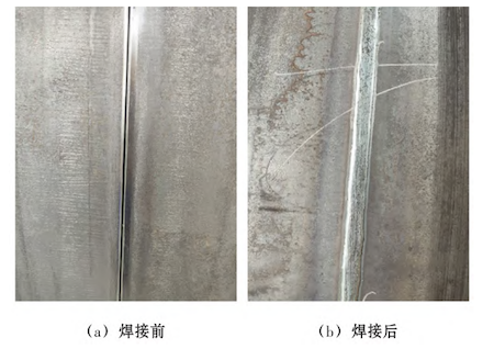
Figure 6. Weld seam quality
(1) Automatic seam tracking technology is a key factor in ensuring pre-welding quality. Through the integration of real-time sensing and dynamic correction, welding quality management can be shifted from reliance on manual intervention toward automated tracking and adjustment.
(2) With continued advances in machine vision, deep learning algorithms, and multi-source information fusion, weld seam position data can be acquired with increasing accuracy, while system response speed and tracking performance continue to improve. Selecting an appropriate tracking method is therefore essential for improving pre-welding quality and advancing fully automated welding.