Check Valve Failures: Causes and Solutions
Check valves are essential non-return devices in industrial piping systems, designed to permit flow in one direction while preventing reverse flow. Although they are often considered relatively simple components because they normally operate automatically without an external actuator, their reliability can have a direct impact on pumps, compressors, heat exchangers, pressure vessels, and downstream process equipment. A malfunctioning check valve may cause reverse flow, water hammer, excessive pressure loss, vibration, leakage, or even equipment damage. For this reason, reliable check valve performance depends not only on valve quality but also on correct selection, installation, commissioning, inspection, and maintenance throughout the valve's service life.
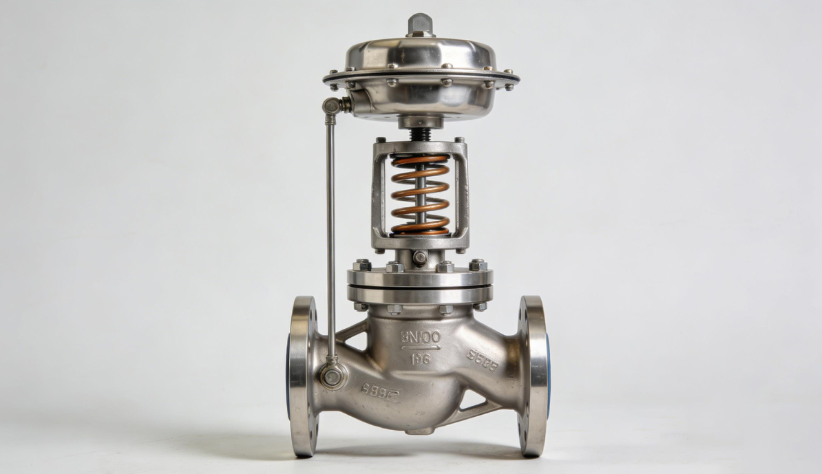
A check valve, also called a non-return valve (NRV) or one-way valve, is designed to automatically respond to changes in flow direction and differential pressure. Unlike a gate valve or globe valve, a conventional check valve normally does not require a handwheel, gearbox, electric actuator, or pneumatic actuator for routine operation. The pressure difference across the valve moves the closure element into the open or closed position.
Under normal forward-flow conditions, upstream pressure and fluid velocity generate sufficient force to lift, swing, or otherwise move the closure element away from the seat. When forward flow decreases or begins to reverse, the pressure differential changes, allowing the closure element to return toward the seat. Ideally, the valve closes quickly enough to prevent significant reverse flow while avoiding excessive impact between the closure element and the seat.
The basic operating principle can be expressed as:
Forward flow → valve opens → reverse flow tendency → valve closes
However, actual valve behavior depends on fluid velocity, pressure differential, closure-element mass, spring force where applicable, piping configuration, fluid properties, and valve design. Therefore, a check valve should not simply be selected according to pipe size and pressure rating. Its dynamic behavior under the actual operating conditions must also be considered.
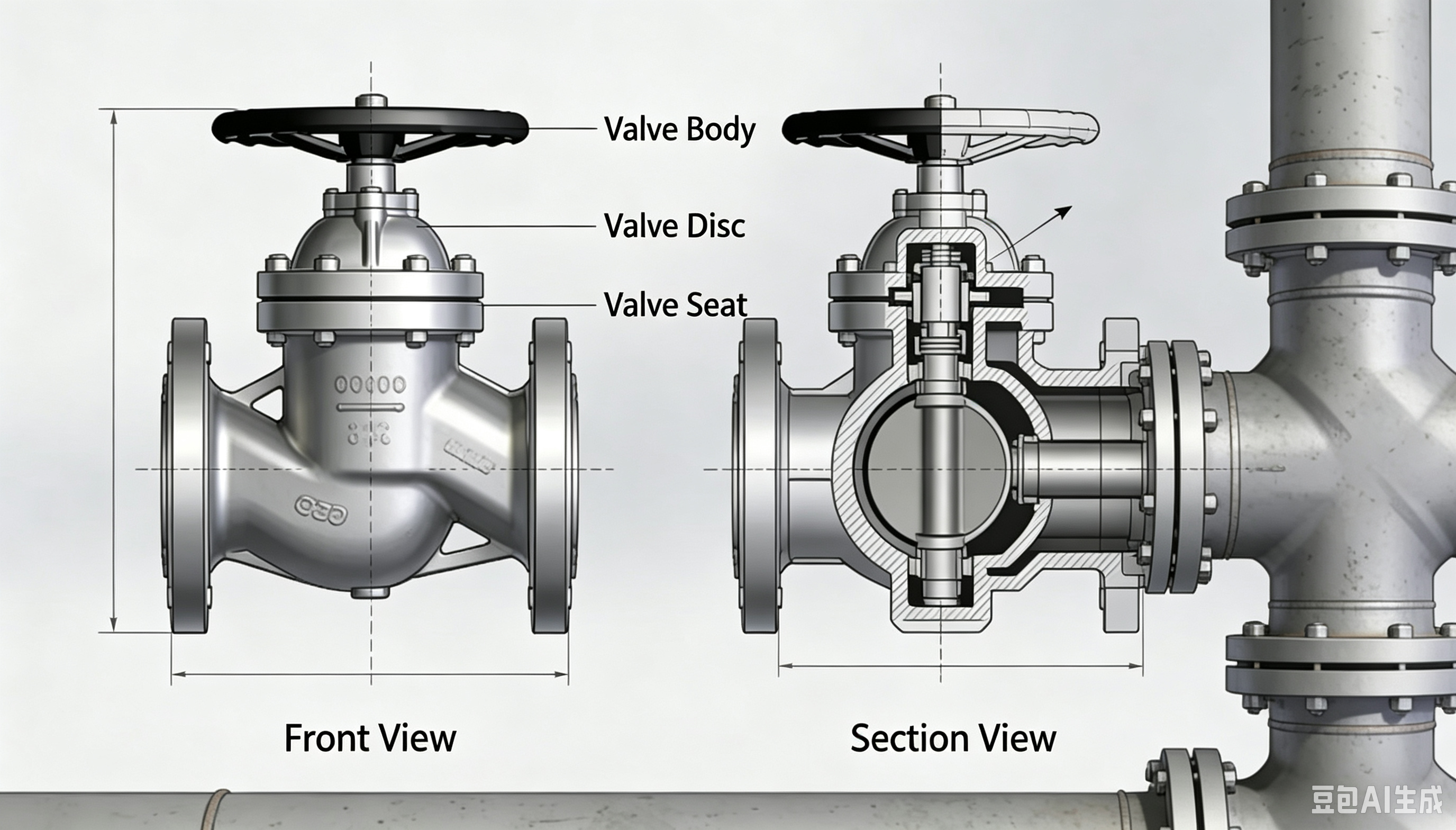
Different check valve designs respond differently to changes in flow. Understanding their mechanical characteristics is important when diagnosing failures because the same system symptom can have different causes depending on valve construction.
A swing check valve uses a disc that rotates around a hinge or shaft. Forward flow pushes the disc away from the seat, while reverse flow causes the disc to swing back toward the seat. Swing check valves generally offer relatively low pressure drop when properly sized because the disc can move substantially out of the flow path.
They are widely used in water, oil and gas, chemical processing, and general industrial piping. However, their performance can be affected by unstable flow conditions. If the flow velocity is too low or fluctuates significantly, the disc may repeatedly move toward and away from the seat. This phenomenon, commonly known as disc flutter, can accelerate wear and produce vibration and noise.
A lift check valve uses a disc or piston that moves vertically relative to the seat. Fluid flowing in the correct direction lifts the closure element, while reverse flow and gravity or spring force return it toward the seat.
Lift check valves can provide effective shutoff and are often suitable for relatively clean fluids. However, their internal passages may be more sensitive to contamination and deposits than some other designs. Incorrect installation orientation can also interfere with the intended movement of the closure element.
Compact wafer-type check valves are frequently selected where installation space and overall valve weight are important considerations. Some designs use a split disc, while others use a single or dual-disc arrangement with springs to promote faster closure.
Their compact construction can be advantageous in pump discharge systems, HVAC applications, water treatment facilities, and industrial process lines. However, spring condition, disc movement, seat condition, and minimum flow velocity all influence operational reliability.
Axial check valves, including nozzle-type designs, guide the closure element along the pipeline axis. Their streamlined flow path can provide favorable flow characteristics and relatively low pressure loss.
These valves are particularly relevant to high-pressure and high-velocity applications where conventional swing-disc movement may create undesirable dynamic effects. Their faster closing characteristics can also make them suitable for applications where reverse flow and transient pressure need to be controlled.
Check valve failures rarely have a single universal cause. A reliable troubleshooting process should connect the observed symptom with the valve design, operating conditions, installation arrangement, and maintenance history.
| Failure Symptom | Common Causes | Typical Consequences |
|---|---|---|
| Reverse flow | Seat damage, disc wear, contamination, incorrect sizing | Backflow, pressure instability, equipment damage |
| Difficult opening | Deposits, corrosion, excessive spring force, incorrect installation | Reduced flow, high pressure drop |
| Vibration or noise | Disc flutter, water hammer, unstable flow | Fatigue, accelerated wear, pipe vibration |
| External leakage | Gasket failure, casting defects, flange problems | Fluid loss, safety and environmental risks |
| Disc sticking | Corrosion, scaling, foreign objects, mechanical damage | Valve fails to open or close |
| Excessive pressure drop | Undersized valve, partially opened disc, deposits | Reduced system efficiency |
| Rapid seat wear | High velocity, cavitation, repeated impact | Increasing internal leakage |
| Corrosion | Incompatible materials or aggressive medium | Loss of mechanical integrity |
This symptom-based approach is particularly useful during field troubleshooting because operators can first identify the abnormal behavior and then investigate the most probable mechanical or process-related causes.
Reverse flow is one of the most important check valve failure modes because the fundamental purpose of the valve is to prevent unwanted reverse movement of the medium. In a pumping system, for example, reverse flow can cause the pump to rotate backward or expose downstream equipment to conditions for which it was not designed.
A valve that does not close properly may allow continuous or intermittent backflow. The problem may initially appear as a relatively small pressure fluctuation, but prolonged reverse flow can increase equipment wear and disrupt process stability.
The valve disc and seat form the primary internal sealing interface. Repeated impact, erosion, corrosion, particulate contamination, or foreign objects can damage these surfaces. Once the contact geometry is compromised, the valve may no longer achieve the required shutoff performance.
High fluid velocity can be particularly damaging because it may cause erosive wear on the seat or disc. In applications containing abrasive solids, such as slurry or contaminated process fluids, this mechanism can become even more significant.
Small particles can become trapped between the closure element and the seat. This prevents full contact and creates a leakage path.
The appropriate corrective action is generally to identify and remove the contamination, inspect the seat and disc for permanent damage, and determine why the foreign material entered the valve. Simply cleaning the valve without addressing upstream contamination may allow the problem to recur.
A check valve that is oversized for the actual flow rate may not operate dynamically as intended. At low flow velocity, the disc may remain only partially open or repeatedly move between positions. This can produce unstable operation and accelerate seat wear.
Therefore, nominal pipe size alone should not determine check valve selection. Flow rate, velocity, pressure, fluid density, viscosity, temperature, and transient conditions should also be evaluated.
A check valve that fails to open fully can create excessive pressure loss and restrict the required flow rate. Operators may observe a higher-than-expected differential pressure across the valve, reduced downstream flow, abnormal noise, or increased pump discharge pressure.
Mineral deposits, rust, process residues, polymerized materials, and other contaminants can accumulate around the disc, hinge, guide, or seat. Over time, these deposits may physically restrict closure-element movement.
This is particularly relevant in water systems with hard water, cooling systems, and process lines carrying fluids capable of depositing solids. Regular inspection and appropriate filtration or upstream separation can reduce the risk.
Corrosion can increase friction between moving components or alter the geometry of the closure mechanism. In a swing check valve, for example, corrosion around the hinge or shaft can prevent the disc from moving freely.
Material selection should therefore consider not only the pressure and temperature rating but also the chemical composition of the process medium, chloride concentration where relevant, oxygen exposure, pH, and other environmental conditions.
Installation orientation is especially important for gravity-dependent or spring-assisted check valve designs. A valve installed in an orientation inconsistent with the manufacturer's requirements may experience restricted disc movement or incorrect closing behavior.
The flow arrow on the valve body should always be checked against the actual piping flow direction. Installation instructions and the manufacturer's specified orientation should take precedence over assumptions based solely on valve appearance.
Vibration and abnormal noise are often early warning signs of dynamic instability. A check valve does not necessarily need to be completely failed to create a problem. Repeated movement of the closure element can gradually produce fatigue and wear.
Disc flutter occurs when the closure element repeatedly oscillates because the flow conditions do not keep it firmly in a stable open position. This can occur when the valve is oversized or operated outside its preferred flow range.
Repeated disc movement may cause:
- Seat impact and wear
- Hinge or shaft wear
- Fatigue of internal components
- Increased pressure fluctuations
- Pipe vibration
- Abnormal noise
A valve that repeatedly flutters should therefore not simply be regarded as a noisy but functional component. The flow regime should be investigated.
Water hammer, or hydraulic shock, is another major source of check valve vibration and noise. When fluid moving through a pipeline is suddenly decelerated, the resulting pressure transient can propagate through the system.
If a check valve closes abruptly after a rapid change in flow, the associated pressure surge may impose substantial loads on the valve, pipe supports, flanges, pumps, and other equipment.
For systems susceptible to water hammer, engineers may consider:
- Selecting a fast-closing or controlled-closing check valve appropriate to the system.
- Using spring-assisted or nozzle-type designs where appropriate.
- Evaluating pump startup and shutdown sequences.
- Installing surge-control equipment where required.
- Reviewing pipe routing, support, and hydraulic characteristics.
The correct solution depends on the complete hydraulic system rather than on the check valve alone.
External leakage differs from internal leakage. Internal leakage occurs through the valve's flow path when the valve should be closed, whereas external leakage involves fluid escaping to the atmosphere through the pressure boundary or connection points.
External leakage can occur at:
- Flanged joints
- Body-to-cover connections
- Bonnet or cover gaskets
- Welded joints
- Body casting defects
- Damaged sealing surfaces
The consequences depend heavily on the medium. Water leakage may primarily create equipment and housekeeping problems, while leakage involving hydrocarbons, toxic chemicals, corrosive fluids, or high-temperature media can create significant safety and environmental concerns.
Improper gasket selection, damaged gaskets, incorrect bolt tightening, flange misalignment, or excessive external loading can contribute to leakage. A new gasket cannot compensate for severely damaged or misaligned flange faces.
During installation, flange faces should be properly aligned, gasket surfaces should be clean, and bolting should follow the applicable installation procedure. Excessive tightening should also be avoided because it can damage certain gasket types or distort components.
A stuck disc can be particularly serious because the valve may effectively become a permanent restriction or fail to provide reverse-flow protection.
Common causes include severe scaling, corrosion, foreign objects, deformation, damaged hinge components, and prolonged periods without operation or maintenance.
In dirty-service applications, the internal geometry should be selected with contamination tolerance in mind. For fluids containing solids, designers may need to evaluate whether a particular check valve design is appropriate rather than simply selecting a standard valve based on pressure class and pipe size.
When a valve becomes stuck, force should not be applied indiscriminately to the external components. Depending on the valve design and service conditions, the correct response may involve isolating the line, depressurizing it, removing the valve, and carrying out a controlled internal inspection.
Preventive reliability begins before the valve reaches the job site. The most effective maintenance program cannot completely compensate for a valve that was fundamentally mismatched to the application.
The fluid should be evaluated for:
- Chemical composition
- Corrosiveness
- Solids content
- Temperature
- Viscosity
- Density
- Gas or liquid phase
- Potential for scaling
- Potential for crystallization
- Abrasive characteristics
For corrosive services, materials such as stainless steels, duplex stainless steels, nickel alloys, or suitable lined constructions may be considered depending on the specific medium and conditions.
The valve's pressure class or pressure-temperature rating must be suitable for the actual operating and design conditions. The evaluation should include not only normal operating pressure but also potential pressure surges.
For industrial valves, specifications such as ASME B16.34 can provide important requirements concerning pressure-temperature ratings, materials, and valve construction. However, the applicable standard depends on valve type, application, and project requirements.
Check valves need sufficient flow to establish stable operation, but excessive velocity can increase erosion, noise, and dynamic loading. An oversized valve may experience unstable disc behavior at low flow, while an undersized valve can generate excessive pressure loss.
Consequently, sizing should consider the valve's flow coefficient, pressure drop, minimum operating flow, maximum flow, and dynamic characteristics rather than relying exclusively on nominal diameter.
Correct installation is a critical part of check valve performance. Even a high-quality valve can experience premature failure if the installation creates unfavorable flow conditions or mechanical stress.
The flow arrow marked on the valve body must correspond to the intended direction of process flow. Installing a check valve backward prevents normal operation and can produce immediate abnormal pressure behavior.
Where required by the valve manufacturer or project specifications, adequate straight pipe length should be provided to establish a stable flow profile. Elbows, tees, reducers, pumps, and other fittings located too close to the valve can generate turbulence and uneven velocity distribution.
Particular attention should be paid to pump discharge applications. Installing a check valve immediately downstream of a pump without considering the pump's flow pattern and the valve's dynamic requirements may increase the risk of vibration and unstable closure behavior.
The piping system should be properly supported and aligned before the valve is installed. Excessive pipe loads can be transferred to the valve body or flanges, potentially causing deformation, connection leakage, or mechanical problems.
Bolting should be tightened using an appropriate sequence and procedure. For critical applications, controlled torque or tensioning methods may be specified.
Check valves are often installed in locations where their internal condition cannot be visually confirmed during normal operation. This makes condition monitoring and preventive maintenance particularly important.
Operators should monitor changes in:
- Differential pressure
- Flow rate
- Valve noise
- Pipe vibration
- Pump behavior
- Pressure fluctuations
- External leakage
- Temperature around relevant components
A sudden change in these parameters may indicate a developing valve problem even before complete failure occurs.
The inspection interval should be based on service severity, valve design, manufacturer recommendations, regulatory requirements, and operating history. Critical valves in severe services may require more frequent inspection than valves operating in clean, stable water systems.
During internal inspection, technicians can examine the disc, seat, hinge, shaft, spring, guide surfaces, and other components for wear, corrosion, deformation, deposits, or foreign material.
When the design permits component replacement, worn seats, discs, springs, pins, gaskets, and other consumable components should be replaced according to the manufacturer's specifications.
Using incorrect replacement materials or dimensions can compromise the original valve design. For critical applications, replacement components should be properly identified and traceable.
When a check valve exhibits abnormal behavior, troubleshooting should follow a structured process rather than immediately removing the valve.
First determine whether the problem is:
- Reverse flow
- Excessive pressure drop
- Failure to open
- Failure to close
- External leakage
- Vibration
- Abnormal noise
- Intermittent operation
Accurate symptom identification helps narrow the possible causes.
Compare actual operating conditions with the valve's design basis. Check pressure, temperature, flow rate, fluid properties, startup and shutdown conditions, and any recent process changes.
A valve that operated reliably for several years may begin to malfunction after a change in pump capacity, flow rate, process medium, or operating procedure.
Inspect the flow direction, valve orientation, flange alignment, pipe supports, nearby elbows and fittings, and visible signs of external damage.
This step is particularly important because not every apparent valve failure originates inside the valve.
If external investigation does not identify the cause, the valve may need to be isolated and inspected internally. The disc, seat, hinge, spring, guide, and sealing surfaces should be examined systematically.
The objective should not simply be to restore temporary operation. The underlying reason for failure should be identified.
For example, replacing a damaged disc without determining why the disc repeatedly impacted the seat may result in another failure. Similarly, replacing a gasket without correcting flange misalignment may only provide a temporary solution.
Industrial check valve selection and quality control should be aligned with the standards applicable to the specific valve type and service. Commonly referenced standards can include API 6D for pipeline and pipeline valves, API 594 for check valves, API 598 for valve inspection and pressure testing, ASME B16.34 for valve construction and pressure-temperature requirements, and relevant flange and face-to-face standards such as ASME B16.5 and ASME B16.10.
The exact standard combination should be determined according to the valve design, pressure class, connection type, industry, project specification, and applicable regulatory requirements. Standards should not be treated as interchangeable labels; each addresses specific technical aspects of valve design, manufacturing, dimensions, testing, or installation.
For procurement, technical documentation should ideally include valve size, pressure class, body and trim materials, end connection, applicable design standard, testing requirements, temperature range, operating medium, and any special requirements concerning fugitive emissions, sour service, fire safety, or corrosion resistance.
| Problem | Primary Investigation | Typical Corrective Approach |
|---|---|---|
| Reverse flow | Seat/disc condition, contamination, sizing | Clean, repair or replace damaged components; reassess sizing |
| Valve will not open fully | Deposits, corrosion, orientation, flow conditions | Clean internal parts, correct installation, review valve selection |
| Disc flutter | Low flow, oversizing, unstable flow | Reassess valve size and design; evaluate flow conditions |
| Water hammer | Closing speed, pump transient, system hydraulics | Optimize valve type and closing characteristics; conduct surge analysis |
| External leakage | Gasket, flange, body, weld | Replace gasket or repair pressure-boundary defects as appropriate |
| Excessive pressure drop | Valve size, deposits, disc position | Clean valve or reassess valve sizing |
| Disc sticking | Corrosion, foreign objects, mechanical damage | Clean, repair or replace internal components |
| Rapid wear | High velocity, cavitation, abrasive medium | Review materials, velocity, valve design, and process conditions |
This type of troubleshooting matrix can be incorporated into a plant's preventive maintenance program, allowing operators and maintenance teams to move from symptom identification to root-cause analysis in a more consistent manner.
The reliability of a check valve is not determined solely by its manufacturing quality. A lifecycle approach is more effective because the valve's operating environment can change significantly over time.
During engineering and selection, the focus should be on fluid characteristics, pressure, temperature, flow velocity, transient conditions, materials, and valve configuration. During installation and commissioning, attention should shift to flow direction, orientation, piping alignment, cleanliness, support, and functional verification.
During operation, condition monitoring can provide early indications of degradation. During maintenance, inspection findings should be documented and compared with previous records. This historical information can help identify recurring failure mechanisms and improve future valve selection.
For example, if a specific check valve repeatedly experiences seat erosion after several months of service, the maintenance team should not simply continue replacing the seat. The engineering team should investigate whether excessive velocity, cavitation, abrasive particles, or an unsuitable trim material is responsible.
The best check valve solution is not necessarily the valve with the most sophisticated construction. Instead, it is the valve whose operating characteristics match the actual hydraulic and mechanical requirements of the system.
For clean water with relatively stable flow, a conventional swing or wafer check valve may be appropriate. For systems where rapid closure and reduced reverse flow are important, spring-assisted or nozzle-type designs may warrant consideration. For dirty or solids-containing fluids, the internal design should be evaluated carefully for clogging and maintenance requirements.
The surrounding piping system must also be considered. Pump characteristics, pipe diameter, flow velocity, elbows, reducers, vertical or horizontal installation, pressure surges, and downstream equipment can all influence check valve performance.
This system-level approach is particularly important in high-pressure oil and gas, chemical processing, power generation, water treatment, and other applications where a check valve failure can have consequences beyond the valve itself.
Although check valves are relatively simple automatic devices, their contribution to industrial piping safety and reliability is substantial. Reverse flow, incomplete closure, difficult opening, disc sticking, vibration, water hammer, excessive pressure drop, and external leakage are among the most common problems encountered in service. These failures can originate from damaged sealing surfaces, contamination, corrosion, improper sizing, unfavorable flow conditions, installation errors, inadequate maintenance, or changes in operating conditions.
A reliable check valve strategy therefore requires more than selecting a valve according to nominal size and pressure class. Correct valve selection, appropriate materials, hydraulic evaluation, proper installation, systematic inspection, and root-cause-based maintenance should work together throughout the equipment lifecycle.
By treating the check valve as part of the complete piping and process system rather than as an isolated component, engineers and maintenance teams can better control reverse flow, minimize pressure losses, reduce vibration and water hammer, and extend service life. For demanding industrial applications, this lifecycle approach provides a practical foundation for safer, more stable, and more efficient piping-system operation.
