The forced valve, also known as double-close double-section and relief function valve, was first used in airport oil depot, mainly used in the metering system, metering calibration system, multi-branch mixed transportation system, tank partition, aviation oil storage and transportation and refueling plug, frequently operated feeding and unloading system, etc. Later, it was gradually used in oil and gas pipelines. Although the proportion of the forced sealing valve in the system is not large, its function and effect are very obvious.
Development of Forced Sealing Valves
In 1946, the American General Valve Company introduced the first generation of A-type series of forced sealing valves, but there were many defects in this series of valves. The operating mechanism was in the medium. If the operating mechanism was repaired, maintained and maintained, it was necessary to stop working and air defense pipelines, which required a lot of manpower, material resources and time. In addition, the soft seal occupies all sealing surfaces. At the same time, the valve is not designed as a fire safety structure. To this end, in 1953, the American General Valve Company introduced an improved B series valve, which was improved as follows: First, the operating mechanism was completely isolated from the conveying medium through gland and packing seal. Secondly, the soft seal is fixed in the groove of the slider by bonding, and the metal slider plays a protective role on the soft seal. The third is to design the fire safety for the valve. By 1958, the new generation of products introduced by the company could realize online maintenance without pipeline shutdown and unloading. After years of development, the currently forced seal valve has made great improvements in valve body sealing, operating mechanism structure, soft seal bonding, fire prevention, heat release system and valve component coating.
In the late 1980s, China began to use imported forced sealing valves. But in the late 1990s, China developed its own forced sealing valves and began to use them in oil depots and aerodromes of civil aviation airports. At present, forced sealing valves have been applied in China's airport aviation, large oil depots, petroleum and petrochemical industries and long-distance pipelines.
Structure and Working Principle of Forced Sealing Valves
The forced sealing valve is mainly composed of the valve, the upper cover, the bottom cover, the slide, the cock and the operating mechanism. The connection between the seal (slide) of the forced valve and the cock adopts the guide rail structure. In the process of opening the valve, firstly, the cock is lifted to a height through the transmission mechanism. With the lifting of the cock, the two slides are gradually pulled back to the center of the valve by the cock. When the sealing surface of the slide is completely separated from the sealing surface of the valve body and a certain gap is formed, the cock and the slide continue to rotate 90 degrees together through the transmission mechanism until the valve is opened. In the closing process of the valve, the cock and the slide are first rotated by 90 degrees through the transmission mechanism (the valve is in the closed state, but no seal is formed), and then the cock is pushed down through the transmission mechanism. With the downward movement of the cock, the slide is pushed closer to the sealing surfaces on both sides of the valve body until the elastic sealing rings on the slide are evenly squeezed to the sealing surfaces on both sides of the valve body to form a seal.
Key technologies of forced valve sealing mainly include the following points:
1. Middle flange seal
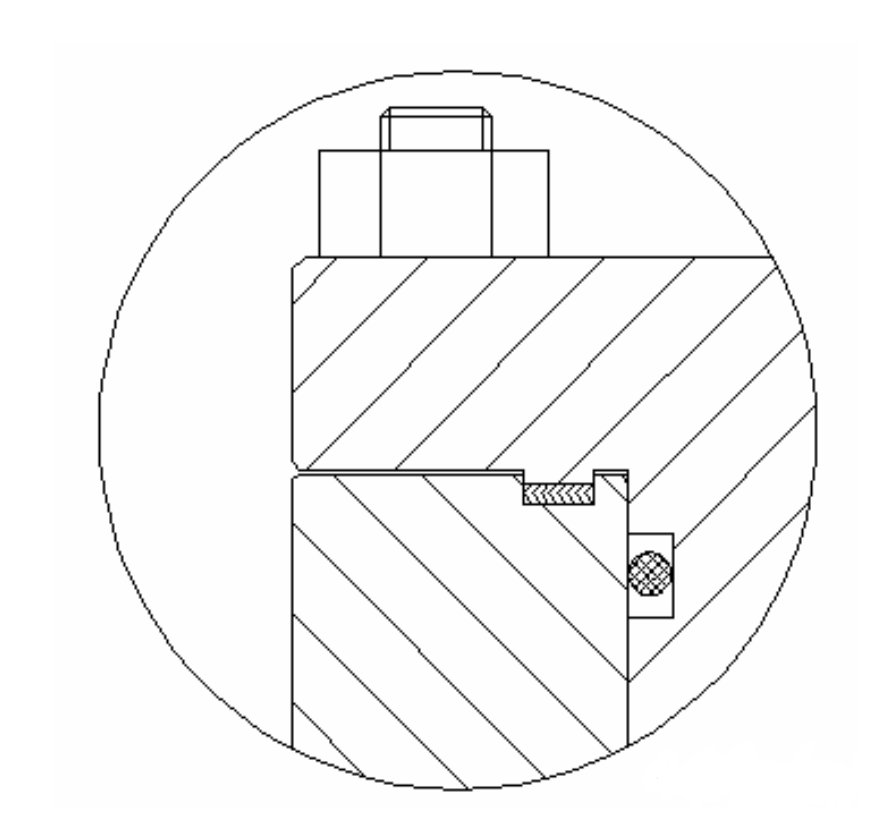
Most of the forced valves are used in aviation kerosene, natural gas, liquefied petroleum gas, refined oil, etc. Because aviation kerosene, natural gas and other media are highly permeable, flammable and explosive, no external leakage of the media must be completely eliminated. The double sealing structure of the O-ring and winding gasket is adopted at the middle flange, as shown in the figure.
2. Packing seal
In the process of opening and closing the valve, the valve core of the forced valve has to move up and down as well as rotate. In addition, due to the particularity of the medium, the packing seal is required to be safe and reliable, and the combined sealing method of inner and outer O-rings and packing seal is often adopted.
3. Overpressure relief function of valve cavity
Double-sealed valves must have relief devices and functions. The pressure difference of relief is caused by the change of ambient temperature. When the double-sealed valve is closed, the medium in the cavity of the valve expands in volume with the increase of ambient temperature, and the pressure gradually increases. If the pressure difference is not released in time, it will have a serious impact on the operation of the valve, and even cause the valve to burst, which will cause serious hidden dangers to the safety of the system. Two-stage valves usually have three pressure relief systems:
(1) Manual pressure relief system (for manually operating valves)
Usually, it is a needle valve installed on the valve body. When the valve is closed, open the needle valve to discharge the medium in the cavity of the valve body to the upstream of the pipeline or the atmosphere.
(2) Differential thermal pressure relief system (for manually and electrically operated valves)
It is a pipeline system with a one-way valve, and a differential thermal pressure relief system is composed of the manual pressure relief valve, three-way valve, one-way valve and isolation valve. The isolation valve remains normally open. When the valve is closed, the overpressure in the cavity of the valve body is discharged upstream of the valve through the one-way valve to connect with the pipeline. At the same time, opening the manual relief valve can check the sealing effect of the valve. When the valve is opened, the manual relief valve must be closed.
(3) Automatic pressure relief system (for electrically operated valves)
When the valve is closed, the pressure relief valve is automatically opened by the operating mechanism, and the valve cavity is communicated with the upstream of the pipeline or the outside world.
4. Operating mechanism and self-locking of the valve
The operating mechanism of the valve adopts a unique L-shaped groove structure, which separates the axial linear movement of the cock from the 90-degree rotation movement, making the valve flexible and light to operate. The cock starts to move linearly and then rotates. In order to reduce the number of turns of the handwheel, generally, the trapezoidal thread of the valve stem and the screw sleeve is double-headed or multi-headed. The gear transmission mechanism is self-locking, and the trapezoidal thread is a heavy trapezoidal thread, which can bear a greater load. There is also a valve, the design of the guide groove is S-shaped, which is nearly an S-shaped spiral line on the cylindrical surface of the screw sleeve. Its action principle is that the cock moves linearly at first, then moves linearly and rotates, and the guide key bears greater shear force, which has high requirements on the strength of the guide key. Moreover, the rotation needs to design a larger stroke, otherwise, it is easy to cause friction between the soft sealing surface and the sealing surface of the valve body, which makes the operating torque larger and shortens the service life of the valve. Therefore, there are fatal design defects in the structure of the "S" guide groove.
5. Special process treatment of key components
Because of the poor working conditions of the valve, it is necessary to carry out special process treatment on the key components of the valve. After machining, the inner cavity of the valve body is plated with hard chromium, so that the inner cavity of the valve body has corrosion resistance, erosion resistance, wear resistance and corrosion resistance. After the slide is machined (before pressing fluororubber), the metal sealing surface of the slide is treated with hard chromium plating, so that it has corrosion resistance, erosion resistance, wear resistance and corrosion resistance. After machining, the cock is treated with nickel plating, and the cock and the upper and lower shafts are resistant to corrosion and corrosion. After rough machining, the valve stem is adjusted. After finishing, it is nitrided to improve the bite resistance and wear resistance of the screw sleeve. The L-shaped guide groove on the screw sleeve and the head of the guide key are quenched after processing to improve the wear resistance and ensure that the guide key can slide freely in the guide groove.
Development of Forced Sealing Valves
In 1946, the American General Valve Company introduced the first generation of A-type series of forced sealing valves, but there were many defects in this series of valves. The operating mechanism was in the medium. If the operating mechanism was repaired, maintained and maintained, it was necessary to stop working and air defense pipelines, which required a lot of manpower, material resources and time. In addition, the soft seal occupies all sealing surfaces. At the same time, the valve is not designed as a fire safety structure. To this end, in 1953, the American General Valve Company introduced an improved B series valve, which was improved as follows: First, the operating mechanism was completely isolated from the conveying medium through gland and packing seal. Secondly, the soft seal is fixed in the groove of the slider by bonding, and the metal slider plays a protective role on the soft seal. The third is to design the fire safety for the valve. By 1958, the new generation of products introduced by the company could realize online maintenance without pipeline shutdown and unloading. After years of development, the currently forced seal valve has made great improvements in valve body sealing, operating mechanism structure, soft seal bonding, fire prevention, heat release system and valve component coating.
In the late 1980s, China began to use imported forced sealing valves. But in the late 1990s, China developed its own forced sealing valves and began to use them in oil depots and aerodromes of civil aviation airports. At present, forced sealing valves have been applied in China's airport aviation, large oil depots, petroleum and petrochemical industries and long-distance pipelines.
Structure and Working Principle of Forced Sealing Valves
The forced sealing valve is mainly composed of the valve, the upper cover, the bottom cover, the slide, the cock and the operating mechanism. The connection between the seal (slide) of the forced valve and the cock adopts the guide rail structure. In the process of opening the valve, firstly, the cock is lifted to a height through the transmission mechanism. With the lifting of the cock, the two slides are gradually pulled back to the center of the valve by the cock. When the sealing surface of the slide is completely separated from the sealing surface of the valve body and a certain gap is formed, the cock and the slide continue to rotate 90 degrees together through the transmission mechanism until the valve is opened. In the closing process of the valve, the cock and the slide are first rotated by 90 degrees through the transmission mechanism (the valve is in the closed state, but no seal is formed), and then the cock is pushed down through the transmission mechanism. With the downward movement of the cock, the slide is pushed closer to the sealing surfaces on both sides of the valve body until the elastic sealing rings on the slide are evenly squeezed to the sealing surfaces on both sides of the valve body to form a seal.
Key technologies of forced valve sealing mainly include the following points:
1. Middle flange seal
Most of the forced valves are used in aviation kerosene, natural gas, liquefied petroleum gas, refined oil, etc. Because aviation kerosene, natural gas and other media are highly permeable, flammable and explosive, no external leakage of the media must be completely eliminated. The double sealing structure of the O-ring and winding gasket is adopted at the middle flange, as shown in the figure.
2. Packing seal
In the process of opening and closing the valve, the valve core of the forced valve has to move up and down as well as rotate. In addition, due to the particularity of the medium, the packing seal is required to be safe and reliable, and the combined sealing method of inner and outer O-rings and packing seal is often adopted.
3. Overpressure relief function of valve cavity
Double-sealed valves must have relief devices and functions. The pressure difference of relief is caused by the change of ambient temperature. When the double-sealed valve is closed, the medium in the cavity of the valve expands in volume with the increase of ambient temperature, and the pressure gradually increases. If the pressure difference is not released in time, it will have a serious impact on the operation of the valve, and even cause the valve to burst, which will cause serious hidden dangers to the safety of the system. Two-stage valves usually have three pressure relief systems:
(1) Manual pressure relief system (for manually operating valves)
Usually, it is a needle valve installed on the valve body. When the valve is closed, open the needle valve to discharge the medium in the cavity of the valve body to the upstream of the pipeline or the atmosphere.
(2) Differential thermal pressure relief system (for manually and electrically operated valves)
It is a pipeline system with a one-way valve, and a differential thermal pressure relief system is composed of the manual pressure relief valve, three-way valve, one-way valve and isolation valve. The isolation valve remains normally open. When the valve is closed, the overpressure in the cavity of the valve body is discharged upstream of the valve through the one-way valve to connect with the pipeline. At the same time, opening the manual relief valve can check the sealing effect of the valve. When the valve is opened, the manual relief valve must be closed.
(3) Automatic pressure relief system (for electrically operated valves)
When the valve is closed, the pressure relief valve is automatically opened by the operating mechanism, and the valve cavity is communicated with the upstream of the pipeline or the outside world.
4. Operating mechanism and self-locking of the valve
The operating mechanism of the valve adopts a unique L-shaped groove structure, which separates the axial linear movement of the cock from the 90-degree rotation movement, making the valve flexible and light to operate. The cock starts to move linearly and then rotates. In order to reduce the number of turns of the handwheel, generally, the trapezoidal thread of the valve stem and the screw sleeve is double-headed or multi-headed. The gear transmission mechanism is self-locking, and the trapezoidal thread is a heavy trapezoidal thread, which can bear a greater load. There is also a valve, the design of the guide groove is S-shaped, which is nearly an S-shaped spiral line on the cylindrical surface of the screw sleeve. Its action principle is that the cock moves linearly at first, then moves linearly and rotates, and the guide key bears greater shear force, which has high requirements on the strength of the guide key. Moreover, the rotation needs to design a larger stroke, otherwise, it is easy to cause friction between the soft sealing surface and the sealing surface of the valve body, which makes the operating torque larger and shortens the service life of the valve. Therefore, there are fatal design defects in the structure of the "S" guide groove.
5. Special process treatment of key components
Because of the poor working conditions of the valve, it is necessary to carry out special process treatment on the key components of the valve. After machining, the inner cavity of the valve body is plated with hard chromium, so that the inner cavity of the valve body has corrosion resistance, erosion resistance, wear resistance and corrosion resistance. After the slide is machined (before pressing fluororubber), the metal sealing surface of the slide is treated with hard chromium plating, so that it has corrosion resistance, erosion resistance, wear resistance and corrosion resistance. After machining, the cock is treated with nickel plating, and the cock and the upper and lower shafts are resistant to corrosion and corrosion. After rough machining, the valve stem is adjusted. After finishing, it is nitrided to improve the bite resistance and wear resistance of the screw sleeve. The L-shaped guide groove on the screw sleeve and the head of the guide key are quenched after processing to improve the wear resistance and ensure that the guide key can slide freely in the guide groove.
News
Industry News
Back to List
