Abstract: In the critical process of silicone production, shut-off ball valves operate under harsh conditions, including high temperature, high pressure, highly corrosive media, and frequent opening and closing cycles. These demanding conditions frequently cause severe failures, such as valve seizure, directly compromising equipment safety and operational stability while markedly reducing production efficiency. Based on real industrial applications, this article systematically examines the primary failure mechanisms of ball valves in such extreme environments, including sealing surface damage, coating degradation, seizure, and both internal and external leakage. Comprehensive solutions are proposed, focusing on material selection, structural design optimization, and enhancement of surface hardening processes. Comprehensive solutions are proposed, focusing on material selection, structural design optimization, and enhancement of surface hardening processes.
Figures 1 and 2 illustrate the process flow and media conditions in the silicone reactor unit of a domestic chemical plant. The reactor operates at 0.35 MPa, with a working medium composed of silicon powder, copper powder, and corrosive high-boiling compounds. Although a nitrogen purge valve is installed for cleaning, frequent jamming of the wear-resistant ball valves—used to dynamically regulate the silicon powder feed—poses a significant risk to safe and stable equipment operation and markedly reduces production efficiency. A thorough investigation into the causes of wear-resistant ball valve failures in the silicone production line is therefore essential. Analysis of process requirements and observed failure modes indicates the operational cycle as follows: the wear-resistant ball valve opens to discharge material whenever the liquid level exceeds a preset threshold. After each discharge, a 0.7 MPa nitrogen purge is manually applied to the pipeline. This discharge cycle occurs approximately every six hours. The working medium is a viscous paste (similar to asphalt) at 200 °C. Upon shutdown and cooling, the medium solidifies into a powder, resulting in alternating high- and low-temperature operating conditions. Consequently, the ball valve must meet stringent requirements for wear resistance, anti-adhesion, anti-clogging, and corrosion resistance. This paper presents a comprehensive solution combining advanced material selection, optimized structural design, and anti-adhesion features for wear-resistant ball valves. This solution provides substantial practical benefits by maintaining reactor media balance, extending valve service life, and minimizing operational safety risks in chemical production.
![]()
Figure 1. Schematic Diagram of the Silicone Workshop Process
![]()
Figure 2. Schematic Diagram of Silicone Media Conditions
During operation, wear-resistant ball valves often suffer from internal and external leakage, sticking, or complete failure to actuate. These issues can compromise valve functionality, trigger system shutdowns, and lead to substantial financial losses for the plant. As the valve operates, powder or catalyst particles adhering to the ball’s surface can become trapped between the valve seat and the ball’s sealing surface. If these particles are harder than the coating alloy, they can scratch the dynamic sealing surface, compromising the valve’s sealing performance (see Figure 3). Moreover, the intrusion of solid particles increases friction between the ball and seat, accelerating wear and significantly increasing the operating torque.
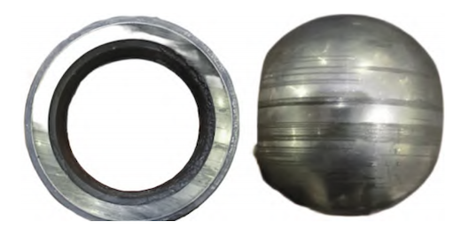
Figure 3 Schematic of Scratches on Ball and Seat Surfaces
If the valve seat is poorly designed, especially lacking dust protection features, powder or catalyst particles can enter the gap between the valve seat and body during operation and gradually accumulate. This accumulation increases resistance to the seat’s micro-movements, raises the initial sealing load, and can ultimately cause spring failure. As shown in Figure 4, deposited material in the spring cavity gradually reduces the spring’s deflection space, leading to loss of elasticity and eventual seat locking. When valve torque increases sharply or locking occurs, the actuator’s high torque can induce metal-to-metal adhesion between the ball and seat, bend or fracture the valve stem, and ultimately lead to internal leakage, sticking, or complete inoperability.
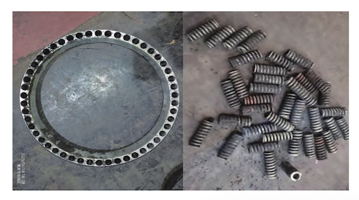
Figure 4 Schematic of Material Accumulation in Spring Cavity
Additionally, poor coating adhesion combined with the corrosive properties of the medium can lead to partial delamination of the hardened coating on the ball and seat surfaces. This degradation increases surface roughness, accelerates wear and scratching of the sealing surfaces, and consequently causes rapid deterioration of sealing performance along with a significant rise in operating torque. Additionally, flaws in the stem sealing design or inadequate packing can permit powder or catalyst particles to enter the interface between the packing and valve stem, increasing wear and significantly reducing the packing’s service life.
During valve maintenance, significant powder accumulation was found in the valve seat cavity, and substantial material crusting was observed on both the valve stem and the lower shaft. To address these issues, a 45°-angled scraper was incorporated on the outer circumference of the valve seat, as shown in Figure 5(a). This scraper automatically removes material from the ball surface during opening and closing, effectively reducing accumulation on the sealing surface and minimizing stress and wear on the valve seat. Figure 5(b) illustrates a closed spring cavity design, where the spring is located at the seat’s interruption point. Flexible graphite sealing rings are installed on both sides of the cavity to isolate it, creating a fully sealed compartment. This design effectively prevents media from accumulating inside the cavity, keeping the seat spring unaffected by the process fluid. Consequently, the spring force remains stable, and the valve seat maintains its flexibility. For small-diameter valves used in applications with heavy oil, powders, or solid particles, disc springs are preferred because of their enhanced dust-proof performance. Additionally, a graphite gasket shaft-seal is installed at the front end of the valve stem cavity to prevent material from entering and accumulating, thereby avoiding stem locking and ensuring smooth, reliable valve operation.
To endure the highly corrosive and volatile nature of silicone media under harsh operating conditions, the packing seal features a multi-composite, low-emission design, as shown in Figure 6. This design facilitates easier assembly and disassembly of the packing using modular, preloaded components, thereby lowering maintenance costs. It also offers outstanding high-temperature resistance (above 300 °C) and cold-flow resistance, ensuring long-term sealing reliability and safe operation throughout the silicone production process.
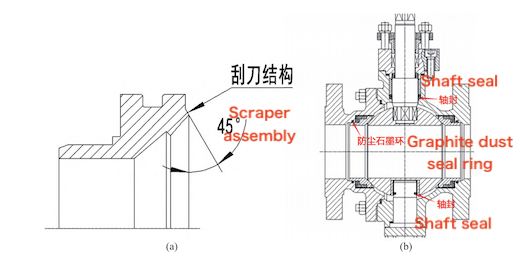
(a) Schematic of the dust-proof scraper (b) Dust-proof design of the valve body
Figure 5: Dust-proof and shaft-sealing structure diagrams
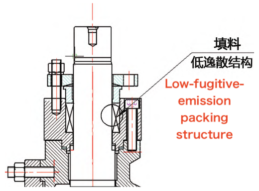
Figure 6: Low-emission packing seal design
The wear-resistant ball valves previously used in silicone plants were made of WCB carbon steel, which suffered severe corrosion. This is due to the presence of highly corrosive substances in silicone production, including chlorides (e.g., HCl), acidic catalysts (e.g., H₂SO₄), and high-temperature steam, all of which accelerate WCB degradation. Corrosion of the valve body generates iron oxides (rust), which elevate friction and wear within the valve, eventually causing seal failure or seizure of the moving components. To address these issues, the valve body has been upgraded to CF3M (316L stainless steel), a highly corrosion-resistant alloy. Its 2–3 % molybdenum content markedly improves resistance to chlorides, weak acids (such as acetic acid, a byproduct of silicone production), and pitting corrosion. CF3M is especially well-suited for media with a pH range of 4 to 9, effectively preventing rust-related increases in friction and component damage, thereby enhancing the valve’s overall reliability and extending its service life.
The wear-resistant ball valves in the silicone workshop operate at approximately 220 °C. To satisfy the stringent requirements for both wear and corrosion resistance, it is crucial to choose a suitable coating material and hardening method. Furthermore, the entire valve flow path should be spray-coated to provide uniform wear protection throughout. As shown in Table 1, CrC (chromium carbide) coatings provide better corrosion resistance than WC (tungsten carbide) coatings, whereas WC offers slightly greater hardness. To achieve both hardness and corrosion resistance, the ball and valve seat undergo a dual hardening process: supersonic CrC spraying followed by ion nitriding, a well-established high-frequency treatment commonly used in wear-resistant ball valves. This dual treatment produces a surface hardness exceeding 70 HRC, delivering exceptional wear and corrosion resistance, with the hardened layer outperforming WC coatings in overall durability and protective capability.
Table 1 Comparison of Hardening Process Performance
|
Hardening Process |
Coating Material |
Effective Coating Thickness (mm) |
Hardness (HV) |
Operating Temperature Range (°C) |
Corrosion Resistance |
|
Ion Nitriding |
Nitride |
0.02–0.03 |
500–1100 |
≤ 300 |
Average |
|
Supersonic Spraying |
WC |
0.2–0.3 |
1000–1400 |
≤ 350 |
Medium |
|
Supersonic Spraying |
CrC |
0.2–0.3 |
800–1000 |
≤ 750 |
Good |
|
Supersonic Spraying |
ST |
0.2–0.3 |
380–800 |
≤ 650 |
Excellent |
|
Flame Spray Welding |
Nickel-Based Alloy |
0.8–1.0 |
300–650 |
≤ 350 |
Good |
|
QPQ Salt Bath |
Nitride, Cyanide |
0.02–0.03 |
600–1100 |
≤ 300 |
Fair |
Before spraying, the ball and valve seat substrates are sandblasted to a Sa 2.5 surface preparation grade. This roughening significantly enhances the coating’s adhesion and mechanical integrity.
The spray welding and spray coating procedures are illustrated in Figure 7:
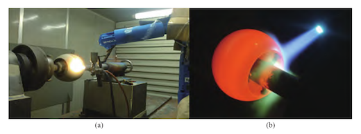
(a) Spray welding process (b) Spray coating process
Figure 7 Schematic of the spray welding and spray coating procedures
During valve maintenance, portions of the valve stem were found twisted at the four corners, and the bottom shaft showed signs of deformation (see Figure 8). This indicated that the original valve stem and bottom shaft materials were insufficiently strong to withstand the higher torque imposed by the granular media. To address this issue, SUS630 martensitic stainless steel was chosen for its high tensile and yield strength, offering enhanced resistance to deformation under the elevated torque caused by granular media. Additionally, the valve stem and bottom shaft were coated with Ni-based or WC materials (hardness ≥ HRC 55) to improve wear resistance and minimize friction between the rotating contact surfaces.
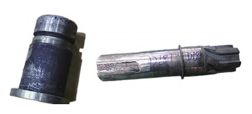
Figure 8 Diagram of valve stem twisting and bottom shaft strain
(1) Coaxiality of the Upper and Lower Shaft Holes of the Valve Body
The “common-axis method” is used to ensure the coaxiality of the upper and lower shaft holes, taking the end faces of the valve body’s inlet and outlet flanges as the reference plane. The upper and lower shaft holes are clamped and machined simultaneously on a horizontal or vertical machining center. Coaxiality must achieve Grade 7 precision, with a maximum coaxiality error of 0.02 mm, meeting the required machining accuracy (see Figure 9).
(2) Positional Accuracy between Shaft Holes and Valve Seat Holes
The geometric relationship between the axes of the valve body’s upper and lower shaft holes and the center position of the valve seat hole is shown in Figure 10. An axial offset subjects the ball core to eccentric forces during rotation, increasing friction with the valve seat or hole wall and potentially leading to jamming. Larger positional deviations resulting from installation or machining errors increase resistance during ball movement, potentially reducing opening and closing flexibility or causing complete seizure. Consequently, the axial offset must be maintained within Grade 7 precision (≤ 0.02 mm).
(3) Symmetry and Perpendicularity of the Ball Core Drive Groove
Deviations in the symmetry or perpendicularity of the ball core drive groove can compromise rotational accuracy, resulting in uneven force distribution between the ball core and valve seat. This uneven loading causes localized stress on the hardened surfaces, accelerating wear. Likewise, misalignment between the valve stem and shaft holes at the upper and lower ends of the fixed ball core can deform or compress the bearings, further increasing valve torque.
(4) Roundness Requirements for the Ball Core and Valve Seat Sealing Surfaces
Deviations in the roundness of the ball core can lead to increased valve torque, while deviations in the roundness of the valve seat sealing surface can negatively affect the sealing performance between the ball and the seat. Any deviation in the ball's roundness will increase valve torque, while deviations in the roundness of the valve seat sealing surface will impair the sealing performance between the ball and seat.
(5) Surface Finish Requirements for Key Components
The ball and valve seat surfaces should have a finish of ≤ Ra 0.2. The valve stem should be polished or cold-rolled to a surface finish of ≤ Ra 0.4, while the mating surfaces between the valve body and valve seat should be extruded to achieve a finish of ≤ Ra 0.4.
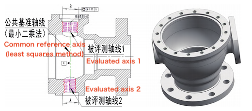
Figure 9 “Common-Axis Method” for Evaluating the Coaxiality of the Upper and Lower Shaft Holes
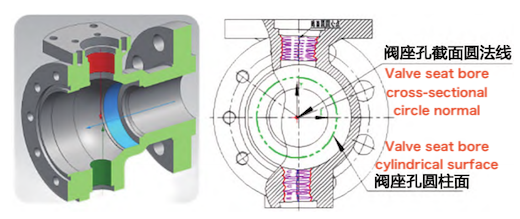
Figure 10 Positional Relationship between the Upper/Lower Shaft Holes and the Valve Seat Hole
The medium in this application behaves like a powder at room temperature and exhibits asphalt-like viscosity at elevated temperatures. Under both conditions, the friction between the valve seat and the ball is considerably higher than that encountered with conventional media. Therefore, when selecting the actuator configuration, the safety factor should be increased from 1.5 to 1.7 to account for the higher friction. To ensure reliable operation, a double-acting actuator—offering higher torque than a single-acting actuator of the same size—is recommended for on-site installation. If a single-acting actuator is used, a two-position, five-way pneumatic control valve may be incorporated. After a period of service, instrument air can be introduced into the spring chamber to increase the closing force and overcome the elevated frictional resistance. The corresponding air circuit configuration is shown in Figure 11.
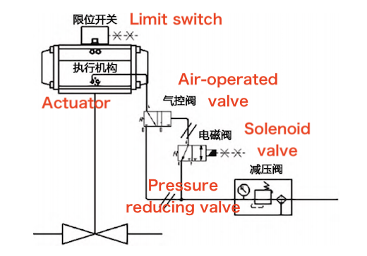
Figure 11 Air Circuit Diagram
By implementing the aforementioned improvements in material selection, structural optimization, precision machining, and actuator configuration, the service life of the repaired valve in this work section increased dramatically—from 3–7 days to over one year. The proposed solution has demonstrated effectiveness under similar operating conditions and can be broadly applied to comparable chemical processes. A comparison of various mainstream valve brands used in the same section is summarized in Table 2.
Table 2 – Performance Comparison of Mainstream Brand Valves in This Work Section
|
Brand |
Service Life |
Improvement Measures |
|
A |
1 year |
Added dustproof design, optimized material selection, and improved machining precision |
|
|
3–7 days |
Forced valve operation with auxiliary air source caused valve stem twisting |
|
B / C / D |
3–7 days |
No improvement |
|
|
1 month |
C-type ball design, unable to achieve bidirectional sealing |
Valves in silicone production workshops frequently fail under highly corrosive and high-viscosity conditions, significantly impacting production continuity and efficiency. To address this challenge, this study systematically analyzed the underlying causes of valve failure, identifying the key failure modes of conventional valves, including exposure to highly corrosive media, material adhesion and clogging, and abnormal wear. A multi-dimensional optimization strategy was implemented, encompassing upgraded material selection, the incorporation of self-cleaning features in the structural design, and the application of optimized surface hardening treatments. Field operation results demonstrate that this solution has substantially improved valve operational stability and significantly reduced failure rates, gaining strong recognition from users. This successful engineering practice provides a valuable reference for equipment selection in demanding industrial processes—such as chemical and pharmaceutical applications—where components must operate reliably under corrosive and high-viscosity conditions. This approach not only ensures long-term stable valve performance but also reduces maintenance frequency, improves production efficiency, and delivers significant economic benefits, promoting broad industry adoption.