Abstract: In accordance with regulations issued by the Ministry of Emergency Management, all inlet and outlet pipelines connected to large, operational oil and gas storage tanks are required to be equipped with emergency shut-off valves. To mitigate safety hazards associated with valves on crude oil storage tanks at a CNOOC onshore terminal, nine manual valves were retrofitted with pneumatic actuators, converting them into emergency shut-off valves. After evaluating actuator characteristics, double-acting pneumatic actuators were selected for installation. These actuators are well-suited for operating large-diameter valves, offering fast response and reliable performance in harsh operating conditions. The manual valves were successfully retrofitted with emergency shut-off functionality online, without any interruption to production. Testing confirmed that the modified valves could fully close the inlet and outlet valves of the crude oil storage tanks within 50 seconds, satisfying the Ministry of Emergency Management’s requirements and effectively mitigating potential safety hazards. Over the past two to three decades, China’s offshore oil industry has grown significantly, marked by the construction of numerous offshore oil platforms. After extraction, oil from these platforms undergoes initial on-site dehydration and degassing treatments before being transported via submarine pipelines to onshore terminals for further processing. Qualified crude oil is subsequently shipped to downstream refineries. Most offshore platforms and onshore terminals were originally designed for a service life of 20 years. Many facilities built in the 20th century have now reached the end of their service life, highlighting the aging of offshore oil equipment and infrastructure. Mitigating the hidden risks posed by obsolete equipment has become a pressing issue in the offshore oil industry. A CNOOC terminal processing plant operates three 50,000 m³ crude oil storage tanks and two 20,000 m³ tanks. The inlet and outlet valves at the base of these tanks are manual slab gate valves, operable only on-site and lacking emergency shut-off functionality. This setup does not comply with the Ministry of Emergency Management’s Basic Requirements for Emergency Shutoff Systems for Oil and Gas Storage Enterprises or with GB50074-2014, Petroleum Storage Design Code. According to these standards, all large aboveground atmospheric storage tanks (tanks with a nominal diameter ≥ 30 m or a nominal volume ≥ 10,000 m³, excluding cryogenic tanks) must be equipped with emergency shut-off valves on all process-material inlet and outlet pipelines directly connected to the tanks. To mitigate potential safety hazards in crude oil storage, nine manual slab gate valves across five storage tanks were retrofitted with emergency shut-off valves. The technology for converting manual valves to pneumatic operation by installing pneumatic actuators is well-established. This article analyzes the characteristics of various actuators, identifies the most suitable option for retrofitting emergency shut-off valves, and ensures that the upgraded valves comply with regulations while effectively mitigating on-site safety risks.
Five inlet and outlet valves of crude oil storage tanks at a CNOOC terminal required retrofitting to include emergency shut-off functionality. The basic data are presented in Table 1.
Table 1. Basic Data of Existing Storage Tanks and Valves
|
Location |
Tank Volume (m³) |
Valve Parameters |
Quantity (units) |
|
T-0101A/B |
20,000 |
DN400 |
4 |
|
T-0202A |
50,000 |
DN700 |
1 |
|
T-0201C/D |
50,000 |
DN700 |
4 |
According to the Ministry of Emergency Management’s Basic Requirements for Emergency Shutoff Systems in Oil and Gas Storage Enterprises, the manual slab gate valves must be retrofitted with a fail-close emergency shut-off function.
Valves are typically automated using either electric or pneumatic actuators. The main characteristics of these actuator types are summarized in Table 2.
Table 2. Types and Characteristics of Valve Actuators
|
Type |
Typical Applications |
Environmental Suitability |
Key Features |
|
Pneumatic |
Linear reciprocating motion; simple design |
Ideal for high-temperature, flammable, or harsh environments |
Simple motion control, fast response, highly reliable under tough conditions |
|
Electric |
Rotary or oscillating motion; compact design |
Requires significant electrical support; sensitive to harsh conditions |
High-precision, multi-point control; less robust in extreme environments |
Since the modification targets the inlet and outlet valves of crude oil storage tanks, which must be converted to fail-close emergency shut-off valves, high-precision control is not necessary. Taking into account the actual site conditions and regulatory requirements, pneumatic actuators were chosen for valve automation.
Pneumatic actuators for valves are generally classified into two types: single-acting and double-acting. Their primary structures and characteristics are summarized in Table 3.
Table 3. Pneumatic Actuator Types and Characteristics
|
Type |
Structure & Operating Principle |
Characteristics |
|
Single-acting spring |
It consists of a cylinder, piston, piston rod, and a return spring. When compressed air enters the cylinder, the piston moves, driving the piston rod to perform the push (or pull) action. When the air supply is stopped, the return spring returns the piston and piston rod to their original positions. |
A return spring is installed at one end of the cylinder. In certain cases, the spring’s durability and reliability can influence the overall performance of the actuator.
|
|
Double-acting |
It consists of a cylinder, piston, and piston rod, without a return spring. Air inlets are provided on both ends of the cylinder. Supplying air to one end while venting the other enables bidirectional motion.
|
It enables bidirectional motion control and provides high flexibility. Its high output force, unrestricted by a spring, makes it suitable for large strokes and heavy loads. The movement speed and stroke length can be adjusted by controlling the air supply pressure and flow rate. |
Since the actuator is installed on the bottom valves of crude oil storage tanks—large valves requiring high torque—a double-acting pneumatic actuator was selected based on the actual operating conditions and the data summarized above. Compared with single-acting spring actuators, double-acting pneumatic actuators equipped with air reservoirs deliver higher output torque, easily managing the opening and closing of large-diameter valves. They also provide rapid response and high positioning accuracy. In contrast, single-acting actuators depend on springs, which can lose elasticity over time, potentially preventing the valve from closing in the event of a malfunction.
Taking a DN700 valve equipped with a pneumatic actuator as an example, the gas tank volume can be calculated using Boyle's law:
Where:
d = diameter of the pneumatic actuator cylinder, 6.5 dm
L = actuator stroke, 7.3 dm
N = number of actuations after the air tank is depleted, 2
b = minimum required cylinder air pressure, 0.7 MPa
c = air compressor startup pressure, 0.4 MPa
V = required gas tank volume
Substituting these values into the formula gives V = 645.96 L. Applying a safety factor of 1.5, the final required gas tank volume is 968.94 L. Consequently, a 1000 L gas tank was selected for the pneumatic actuator installed on the DN700 valve. The gas tank ensures that the actuator can maintain valve position in the event of a gas supply failure, thereby enhancing system reliability and safety.
Valve Preparation and Actuator Transport: Identify the retrofit location and deliver the corresponding pneumatic actuator to the installation site. Before installation, ensure that the tank is not in service for gathering or transportation. Adjust the existing manual flat gate valve to either the fully open or fully closed position to ensure proper operation once the actuator is installed. This ensures that the valve can fully open and close when the actuator reaches its limit position. Reducer Removal: As shown in Figure 1, once the above preparations are complete, remove the handwheel mechanism from the existing manual flat gate valve. Using a wrench, remove the eight bolts securing the reducer, then carefully lift it off and set it aside. Ensure dust protection is in place to prevent contamination of the valve body. Finally, remove the gasket between the reducer and the original valve.
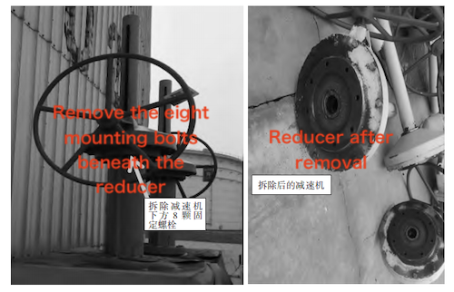
Figure 1. Reducer Removal
Pneumatic Actuator Installation: As shown in Figure 2, position the new gasket on the valve seat. Hoist the pneumatic actuator above the valve, then align the main shaft with the lead screw. Connect the actuator bracket to the fixed bracket, ensuring a firm and secure connection. During installation, tighten the bolts or nuts evenly in a crisscross pattern to prevent excessive stress.
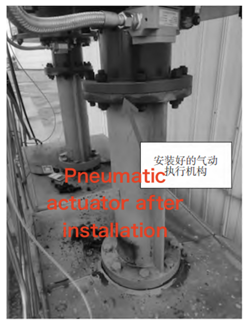
Figure 2: Pneumatic Actuator Installation
Gas Pipeline Connection: As shown in Figure 3, install the piping on-site according to the design, ensuring that all connections are properly sealed. Connect the main air source, signal air source, and actuator instrument panel as shown in Figure 4. The air source inlet, located outside the cofferdam, is divided into two paths, as illustrated in Figure 5. One path passes through a check valve into the gas storage tank, providing both drive and signal gas. From the gas storage tank, the gas flows through a filter-pressure reducing valve and then a pneumatic control valve, which powers the pneumatic actuator cylinder. After the filter-pressure reducing valve, the gas line connects to a tee, then to a solenoid valve, a lock valve, and finally the gas control valve, which regulates the opening and closing of the actuator. Under normal conditions, the solenoid valve stays open, allowing gas to flow to the lock valve and keeping the valve in the open position. Remote electrical signals control the solenoid valve, which in turn regulates gas flow to the lock valve. When the flow to the lock valve is blocked, the valve closes. Another gas source functions as the signal gas (Figure 6). It passes through a manual valve outside the cofferdam, then through a fusible plug, and finally enters the lock valve. This setup allows personnel to manually control the pneumatic actuator by regulating the gas flow to the lock valve. The fusible plug cuts off gas flow to the lock valve in the event of high temperatures or fire, enabling emergency shutoff of the crude oil storage tank valve.
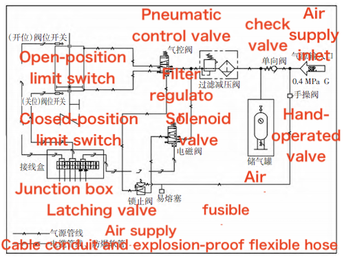
Figure 3: Air Circuit Design
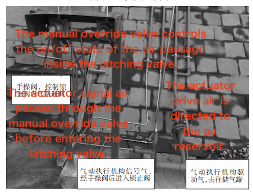
Figure 4: Air Source Connection Diagram
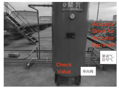
Figure 5: Gas Tank Route Diagram
Cable Connection: Connect the control and signal cables following the actuator’s electrical wiring diagram, and verify insulation resistance to ensure correct and safe installation. Connect the two cables exiting the actuator’s explosion-proof junction box—the valve position signal cable and the solenoid valve control cable—to the central control system, ensuring secure and correct connections. Make sure all connections are secure to prevent malfunctions caused by loose or incorrect wiring.
Functional Check: Before supplying air, perform a functional test of the actuator to ensure it operates smoothly without sticking or abnormal noises.
Commissioning and Acceptance: During commissioning, carefully observe the pneumatic actuator’s operation and feedback signals. Test the valve’s automatic shutoff function using both the manual valve and the remote solenoid valve from the central control system. The total time from fully open to fully closed was 50 seconds, meeting the Ministry of Emergency Management’s "Basic Requirements for Emergency Shutoff Systems in Oil and Gas Storage Enterprises" and demonstrating the effectiveness of the retrofit.
Based on the pneumatic circuit diagram shown in Figure 3, the valve retrofitting process is as follows:
Normal Operation: When the solenoid valve is energized, it opens, allowing air to flow through the latching valve, which then signals the air-controlled valve to open. When the solenoid valve loses power, it switches, and the latching valve signals the air-controlled valve to close.
Electrical Fault: In the event of an electrical fault, the solenoid valve loses power, the latching valve receives a signal, and the valve closes automatically.
Gas Fault: If a gas supply fault occurs, the latching valve receives a gas-loss signal, triggering the valve to close.
Fire Event: If high temperatures activate the fusible plug, it sends a gas-loss signal to the latching valve, causing the valve to close.
Emergency Manual Shutoff: Opening the manual valve sends a gas-loss signal to the latching valve, causing the valve to close.
In summary, retrofitting the manual valve with a pneumatic actuator to create an emergency shutoff valve meets the Ministry of Emergency Management’s “Basic Requirements for Emergency Shutoff Systems in Oil and Gas Storage Enterprises.” The pneumatic actuator must be of the fail-close (FC) type.
The valve was retrofitted in situ with a pneumatic actuator, transforming it into an automatic valve and enabling automated operation. This study analyzed actuator characteristics and implemented a pneumatic retrofit on the existing manual valve, granting it emergency shutoff capability. The following conclusions were drawn:
- After comparing electric and pneumatic actuators, a double-acting pneumatic actuator was chosen for its suitability for large-diameter valves, fast response, and reliable performance in harsh operating conditions.
- The double-acting pneumatic actuator was retrofitted to the manual valve online, avoiding production downtime. Once the air pipeline and electrical wiring were connected, the crude oil storage tank valve gained full emergency shutoff functionality.
- Post-installation testing confirmed that the valve achieved an emergency shutoff within 50 seconds, effectively mitigating the potential safety hazard.