Abstract: To investigate stem blow deformation in high-temperature, high-pressure globe valves caused by high-speed fluid impact during opening, numerical simulations were performed to analyze stem forces and deformation under nitrogen conditions of 1700 K and 200 MPa. The Redlich–Kwong real-gas equation of state was used to model nitrogen properties, and the Realizable k–ε turbulence model was employed. The results show that the lateral impact force on the stem peaked at 310.16 kN during initial opening, causing a maximum deformation of 1.1986 mm at the stem base. Significant stress concentration occurred at the stem–support connection, with a maximum equivalent stress of 156.52 MPa, indicating a potential weak point in the structural design. As the valve approached full opening, the lateral force on the stem reversed direction. This study provides guidance for evaluating the structural integrity and fatigue life of globe valve stems, as well as for optimizing the design of the support structure.
Globe valves are essential components for regulating fluid flow in industrial systems. As process industries advance, extreme operating conditions—such as high temperatures and high pressures in aerospace, petrochemical, and nuclear power applications—present significant challenges to the stability and reliability of these valves. When the working medium is a high-temperature, high-pressure gas, the outer surface of the valve core is directly subjected to the gas’s normal impact during opening. This impact induces lateral deformation of both the valve core and the stem, leading to stem blow deformation.
The industry has devoted significant attention to the strain and deformation that occur during the operation of various specialty valves, including high-temperature, high-pressure globe valves. Wu Binbin et al. studied the strain of a DN3000 large-diameter butterfly valve under deadweight, internal pressure, and torque, and assessed its structural rigidity. Zhang Jun et al. used a thermal–fluid–structure coupling approach to investigate the thermal deformation of a hydraulic slide valve core and explored strategies to reduce this deformation. Sun Shuaijun et al. optimized the design of a polytetrafluoroethylene (PTFE) valve seat and proposed measures to improve its stiffness, while Liu Yuping et al. investigated the deformation of a cryogenic ball valve seat under different temperature conditions and offered engineering recommendations for the sealing surface width. Yu Xiaoguang et al. enhanced the metal seal ring of a triple-eccentric butterfly valve, increasing its deformation capacity and thereby improving its sealing performance. Ghosh et al. designed a valve core for a high-pressure differential flow control plunger pump and analyzed its stress and strain distribution, while Chen et al. proposed a valve orifice thermal deformation optimization algorithm based on measured data to accurately predict thermal deformation in hydraulic valve orifices. Tao Yong et al. investigated the deformation of a high-pressure multi-way valve body using a fluid–structure interaction approach and found that the maximum deformation occurred at the junction between the pressure compensation chamber and the reversing valve chamber. Guo Jiali et al. simulated and analyzed the effects of preload torque on the stress and strain of an end cover structure, concluding that excessive preload torque can lead to material damage in the end cover. Zhao Tianwu investigated the deformation and internal leakage of an electro-hydraulic servo valve under varying sea depth conditions, finding that the clearance between the slide valve and the valve sleeve decreases as the depth increases. Chen et al. analyzed the stress and strain of a nuclear-grade valve under seismic loading to ensure its reliable operability during emergency or disaster conditions. Based on this research background, it is evident that simulation methods for analyzing stress and deformation in specialty valves are well established, and the risks associated with excessive deformation have been thoroughly investigated. However, most existing studies focus on the overall structure of specialty valves, including valve seats, orifices, and nozzles, while research on the deformation of globe valve stems caused by high-speed impacts from high-temperature, high-pressure gas is still limited. Since the high-temperature, high-pressure globe valves examined in this study operate under extremely harsh conditions, the risk of excessive stem deformation is high, posing significant hazards; therefore, further investigation is essential to ensure system safety.
The structural cross-section of the globe valve is shown in Figure 1(a). The valve primarily consists of a body, stem, valve core, seat, inlet and outlet sections, central cavity, thermal insulation components, and connectors. The globe valve serves two primary functions. First, prior to system operation, during heater warming and pre-pressurization, it isolates the high-temperature, high-pressure gas inside the heater from the downstream pipeline, thereby satisfying heating and sealing requirements and ensuring downstream safety. Second, during system operation, the valve allows rapid opening and closing to regulate or stop gas flow as needed. Figure 1(b) presents a cross-section of the globe valve stem. An internal cooling channel permits the circulation of cooling water through the stem during operation, preventing overheating. The primary material properties of the valve stem are listed in Table 1.
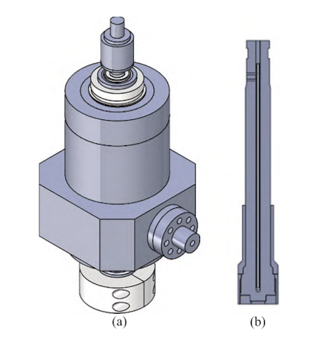
(a) Overall cross-section (b) Valve stem cross-section
Figure 1. Schematic diagram of the ultra-high-pressure globe valve model
Table 1. Main material parameters of the valve stem
|
Component |
Material |
Density (kg/m³) |
Thermal expansion coefficient (1/°C) |
Young’s modulus (GPa) |
Poisson’s ratio |
Yield strength (MPa) |
Tangent modulus (GPa) |
Thermal conductivity (W/(m·°C)) |
Specific heat (J/(kg·°C)) |
|
Valve stem |
GH4169 |
8220 |
1.44 × 10⁻⁵ |
165 |
0.30 |
648 |
3 |
11.90 |
421 |
|
Support |
GH4099 |
8470 |
1.53 × 10⁻⁵ |
204 |
0.31 |
419 |
80 |
|
|
The working medium inside the globe valve is nitrogen at 1700 K and 200 MPa. Due to the high flow velocity of nitrogen through the pipeline, gas compressibility cannot be neglected, rendering the ideal gas model unsuitable. Instead, the Redlich–Kwong (R–K) equation of state, based on the van der Waals equation, is employed to accurately approximate the behavior of real gases. This equation offers an accurate representation of gas behavior under high-pressure and ultra-high-pressure conditions. The general form of the Redlich–Kwong (R–K) equation is:

Where:
P — gas pressure (Pa)
V — molar volume (m³/mol)
T — temperature (K)
R — gas constant (J/(mol·K))
a — intermolecular attraction correction constant (determined by the virial coefficient)
b — volume correction constant (determined by the virial coefficient). According to the R–K equation of state, at 1700 K, nitrogen has a density of 277.667 kg/m³, a thermal conductivity of 0.115 W/(m·K), and a dynamic viscosity of 6.586 × 10⁻⁵ Pa·s.
To facilitate computation, the model was simplified by dividing the full stroke of the globe valve—from fully closed to fully open—into fifteen equal segments, with separate flow domain models established for each segment. The lateral force acting on the valve stem was calculated for the maximum impact flow rate in each segment, and the overall maximum force was determined, as illustrated in Figure 2. Exploiting symmetry, only half of the flow domain was modeled for the calculations. The flow domain was discretized using a tetrahedral mesh with a 10 mm cell size, as depicted in Figure 3. For the solid-domain valve stem, a hybrid mesh with a 10 mm cell size was used, as illustrated in Figure 4.
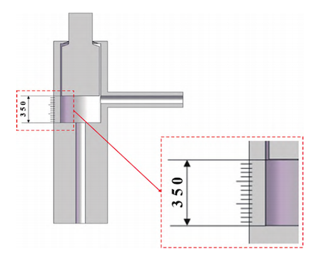
Figure 2 Simplified model of DN125 globe valve with fifteen equally divided points
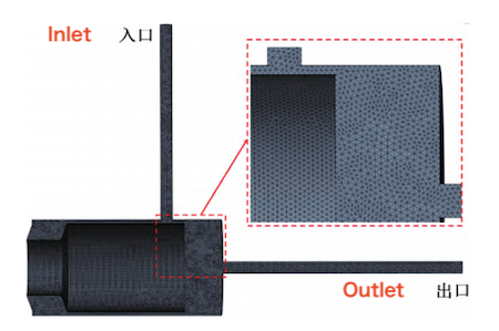
Figure 3 Flow domain mesh generation
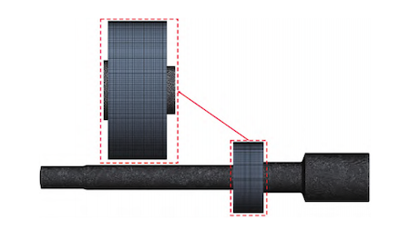
Figure 4 Valve stem mesh generation in the solid domain
For the fluid domain, the inlet was specified as a pressure boundary with 200 MPa and 1700 K, the outlet as a mass-flow boundary with 182.5 kg/s, and all walls were assigned no-slip conditions. Preliminary calculations indicated that the Reynolds number inside the valve was on the order of 10⁷, confirming a turbulent flow regime and requiring the use of an appropriate turbulence model. Eddy-viscosity models based on the Boussinesq approximation are widely used in engineering, and considering both computational efficiency and accuracy, the Realizable k–ε model was selected. For the fluid domain solution, a pressure-based solver was employed, with the standard wall function applied for near-wall treatment. Density, momentum, and energy were discretized using a second-order upwind scheme, while pressure was discretized using a second-order scheme. Gradients were computed using the Green–Gauss method, and pressure–velocity coupling was performed with the Coupled algorithm. Convergence was considered achieved when two conditions were met: (1) the residuals of all governing variables were below 10⁻³, and (2) the average flow rate at the valve inlet remained stable, with fluctuations of less than 1%. For the solid domain, to simulate the valve stem's actual operating conditions, the upper end face of the stem and the outer surface of the hollow cylindrical support were defined as fixed supports. A normal force was applied to the valve core surface (i.e., the fluid impact surface), with a magnitude equal to the maximum impact force on the stem obtained from the flow-field simulation (Figure 5).

Figure 5 Boundary condition setup for static analysis of the valve stem
Figure 6 shows the force exerted on the valve stem by the maximum impact flow at the inlet of the ultra-high-pressure globe valve during its opening. At the initial stage of opening, the valve stem experiences the greatest impact, with a maximum normal force of 310.16 kN occurring at an opening displacement of 23 mm. As the valve opens further, the force decreases in a fluctuating pattern. Near full opening (opening displacement > 300 mm), the direction of the impact force reverses. This reversal occurs because the inlet velocity increases sharply as the valve opens, leading to a local pressure drop that reduces the positive normal force on the stem. Simultaneously, a low-velocity region develops on the back side of the stem, resulting in high static pressure that produces a reverse force. When this reverse force exceeds the forward impact force, the net normal force on the stem becomes negative. Structural static analysis was performed using the fluid force results. The maximum normal deflection of the stem during opening is shown in Figure 7(a), and the maximum equivalent stress is presented in Figure 7(b). The spatial distributions of total deformation and equivalent stress of the valve stem are shown in Figure 8. As shown in Figure 7, the maximum deflection of the stem under the peak normal fluid force of 310.16 kN is 1.1986 mm, located at the bottom of the stem. The maximum equivalent stress reaches 156.52 MPa, concentrated at the junction between the stem and its support. Notably, in Figure 7(a), when the valve is nearly fully open, the maximum normal deflection becomes negative, corresponding to the reversed fluid force shown in Figure 6. Figure 8 shows that the maximum deformation occurs at the stem base, potentially compromising its long-term durability. Significant stress concentration is observed at the stem–support contact region, especially on the side opposite the stem. This suggests that the support is a critical site for stress transmission and could constitute a structural weak point. Overall, the deformation and stress distribution indicate that the stem experiences substantial dynamic loading during opening, particularly in the region near the valve body. Therefore, the stem–support interface should be carefully designed and optimized to minimize stress concentration, prevent potential damage, and enhance the valve stem’s long-term service life.
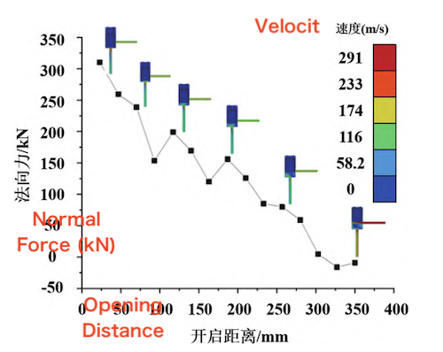
Figure 6. Normal fluid force acting on the valve stem during the opening process
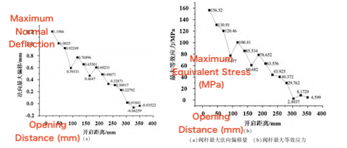
Figure 7. Maximum normal displacement and maximum equivalent stress of the valve stem during opening
(a) Maximum Normal Deflection of Valve Stem (b) Maximum Equivalent Stress of Valve Stem
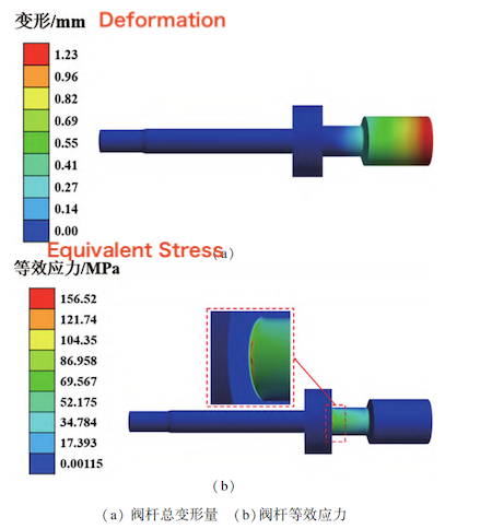
Figure 8. Total deformation and equivalent stress distribution of the valve stem
(a) Total Deformation of Valve Stem (b) Equivalent Stress of Valve Stem
This paper investigates the phenomenon of stem blow deformation in a globe valve caused by high-temperature, high-pressure fluid impact. Using both fluid- and solid-domain analyses, the full stroke of the valve was divided into fifteen equal segments. The variation in normal force exerted by high-temperature, high-pressure, high-velocity nitrogen on the stem at different valve openings was calculated, and the resulting displacement, stress, and deformation of the stem were analyzed, leading to the following conclusions:
- During normal operation, the normal force exerted by the fluid on the stem of the ultra-high-pressure globe valve fluctuates while generally decreasing. The maximum force of 310.16 kN occurs at an opening displacement of approximately 20 mm between the stem base and the valve body, where the stem experiences a maximum deformation of 1.1986 mm at the base, potentially affecting its long-term durability.
- When the valve nears full opening, the normal force at the inlet reverses direction, causing the stem to deform oppositely, and thus fatigue life must be carefully considered in the design.
- Throughout the opening process, the stem is subjected to substantial impact forces and stresses, with pronounced stress concentration at the stem–support interface, a critical stress-transfer area that may constitute a structural weak point. Careful consideration of the service life of this region is essential to prevent potential damage or premature wear.