Posted Jul 29, 2022
Medium Flow in High-Temperature Wear-resistant Ball Valves
The ball valve is widely used in various energy transmission systems as a regulating component to control the flow rate and make and break the pipeline system. When the ball valve is applied to the harsh conditions of high temperature and high pressure in the pipeline flowing medium containing catalyst particles, the catalyst particles in the medium will have a very important impact on the overall performance of the ball valve, and the performance of the ball valve will directly affect the reliability and safety of the conveying system. In the previous research, the author introduced a kind of high-temperature wear-resistant ball valve, and it has been widely used in harsh working conditions containing solid catalyst particles such as pneumatic conveying and fluidized bed residue hydrogenation. This paper will further study this kind of high-temperature wear-resistant ball valve.
Physical model and numerical simulation method
1. Physical model
The high-temperature wear-resistant ball valve used in this research is independently developed by the valve designers of Zhejiang Petrochemical Valve Co., Ltd., and its three-dimensional structure is shown in Figure 1. High-temperature wear-resistant ball valve mainly includes a valve body, valve cover, valve stem, bracket, ball and other structures.
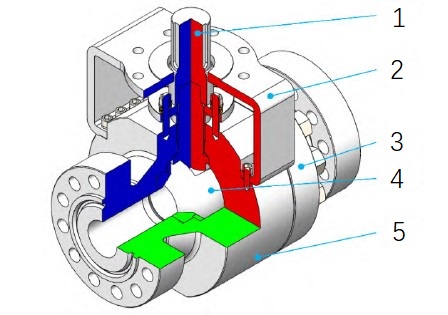
Figure 1 Three-dimensional structure diagram of high-temperature wear-resistant ball valve
1. valve stem 2. bracket 3. valve cover 4. ball 5. valve body
By extracting the flow passage inside the high-temperature wear-resistant ball valve, the flow area of residual oil medium inside the wear-resistant ball valve and the pipeline is obtained, and it is used as the calculation domain of this numerical simulation study. Figure 2 shows the schematic diagram of the internal flow passage of the high-temperature wear-resistant ball valve at 50% opening. The internal channel is mainly divided into three parts: the upstream pipeline area, the wear-resistant ball valve cavity area and the downstream pipeline area. Both the upstream pipeline area and the downstream pipeline area extend to a distance of 10 times the diameter of the pipeline, so as to ensure that the residual oil medium and catalyst particles in the calculation can fully develop.
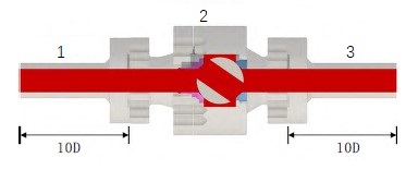
Figure 2 Schematic diagram of the internal flow passage of high-temperature wear-resistant ball valve with 50% opening
2. Numerical simulation method
In this paper, the Euler-Lagrange method is used to calculate the coupling between the residue medium and catalyst particles. The residue flow field is solved by the incompressible Navier-Stokes equation, and the interaction between fluid and particles is added to the momentum equation. The Realizable k-epsilon model is used to solve the turbulent flow. The governing equation of the continuous phase is as follows.
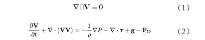
Where V is the velocity of the residual oil medium, ρ is the viscosity of the residual oil medium, P is the pressure, τ is the stress tensor, G is the gravity, and FD is the drag resistance of particles. The motion equation of catalyst is solved by Newton's second law, and the pressure gradient force, virtual mass force, Magnus force and viscous shear force of solid catalyst are not considered. Therefore, the drag resistance and gravity of fluid to particles are mainly used to predict the motion of particles. According to Clift et al.' s research, the motion equation of particles can be written as:

Where represents the gravity of the particles. Drug resistance is the most important force of gas acting on particles, which is defined as:

Where Cd is the resistance coefficient, and its formula is given by Morsi and Alexander.
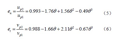
In the process of movement, the particles will collide with the wall and rebound, which will cause the particles to lose some kinetic energy. Therefore, the formula proposed by Grant et al. is used to solve the velocity after particles collide with the wall, and the normal recovery coefficient en and tangential recovery coefficient ET are used to reflect the change of tangential and normal velocity after particles collide with the wall:
In this study, the inlet velocity of residue and catalyst particles is 5 m/s, and the residue medium is Tahe atmospheric residue with a density of 1018.7 kg/m3 and a viscosity of 0.008 262 kg/m-s; The catalyst particles are spherical particles supported by Al2O3, with a diameter of 200μm and a density of 3 650 kg/m3.
Results discussion
1. Verification of grid independence
The computational domain shown in Figure 2 is divided by tetrahedral unstructured grids, and five sets of grids with different numbers are obtained: 800,000, 1 million, 1.2 million, 1.6 million and 2.2 million. When the wear-resistant ball valve is 100% open, five sets of grids are calculated, and the average flow velocity in three calculation domains is obtained. Through comparison, it can be found that when the number of grids exceeds 1.2 million, the correlation between the calculation results and the number of grids is very small. Therefore, this paper uses 2.2 million grids for calculation.
2. Residual oil flow analysis
When the relative opening of the wear-resistant ball valve is 100%, the velocity in the pipeline is relatively uniform. However, due to the viscosity of the residual oil, the wall of the pipeline and the wall of the ball valve has a relatively large viscous force against the flow of the residual oil, which makes the velocity of the residual oil in the middle of the pipeline faster than that on the wall of the pipeline, and the velocity of the residual oil will be lower at the matching positions of the front valve seat and the bonnet, the ball and the front valve seat and the rear valve seat. When the relative opening of the wear-resistant ball valve is 75%, the velocity of residual oil in the middle of the pipeline is still higher than that near the wall, but in the downstream pipeline, the velocity at the bottom of the pipeline is higher than that above the pipeline. In the middle part of the ball of the wear-resistant ball valve, the residual oil velocity in the lower part of the pipeline is lower than that above the pipeline. When the relative opening of the wear-resistant ball valve is 50%, the residual oil has entered the valve cavity and has a very low flow rate in the valve cavity. However, with the decrease of the flow area between the ball valve and the front valve seat, the residual oil forms a high-speed jet when passing through the ball valve, and the high-speed jet hits the upper wall of the valve core pipeline, and sticks to the wall of the valve core pipeline and enters the downstream pipeline, forming a very obvious vortex in the upper half of the downstream pipeline. When the relative opening of the wear-resistant ball valve is 25%, the flow area between the ball and the front valve seat is further reduced, and the throttling effect of the valve is very strong, which makes the high-speed jet in the pipeline more obvious than when the relative opening is 50%, and the high-speed jet will also be close to the wall of the pipeline. When the wear-resistant ball valve is fully open, the relative pressure in the pipeline is relatively small, and the pressure difference between the front and rear positions of the ball is not very large. However, with the decrease of the opening of the wear-resistant ball valve, the pressure in the upstream pipeline gradually increases and the pressure in the downstream pipeline gradually decreases, and the pressure difference between the front and rear of the ball will become very large.
3. Particle distribution near the ball valve
When the relative opening of the wear-resistant ball valve is 100%, the catalyst particles in the residual oil medium can be evenly distributed in the pipeline. With the decrease in the opening of the wear-resistant ball valve, the concentration of catalyst particles in the high-speed area of the ball valve spool pipeline gradually increases. Especially when the relative opening of the wear-resistant ball valve is 50% and 25%, the particles will tend to be near the spool wall under the carrying effect of the high-speed jet of residual oil. It can also be found that there are very few particles in the low-speed area of the spool. When the valve cavity appears, the number of particles near the valve cavity in the low-speed area of the valve core is also relatively small. However, the number of particles will be very large near the valve cavity in the high-speed area of the valve core. The distribution of catalyst particles in the downstream pipeline is quite extreme, that is, the concentration of particles near the sphere at the bottom and upper part of the downstream pipeline is very high.
4. Particle velocity and motion analysis near the wear-resistant ball valve.
Fig. 3 shows the velocity vector diagram of catalyst particles when the relative opening of the wear-resistant ball valve is 100% and 75%. It can be seen from the figure that when the relative opening of the wear-resistant ball valve is 100%, the movement direction of catalyst particles is relatively uniform, mainly along the flow direction of a residual oil medium in the pipeline, and the velocity of catalyst particles in the pipeline is higher than that near the wall. When the relative opening of the wear-resistant ball valve is 75%, it can be inferred from the velocity vector diagram of the particles that the catalyst particles circulate below the spool pipe and above the downstream pipe. The circulating flow of catalyst particles above the downstream pipeline will be more obvious, and the catalyst particles also form a high-speed particle flow at the bottom of the downstream pipeline. Combined with the particle distribution, it is not difficult to speculate that the high concentration distribution at the bottom of the downstream pipeline is caused by the particles following the high-speed jet of residual oil, and the high concentration particles near the sphere at the upper part of the downstream pipeline are caused by the accumulation of particles due to the circular movement of particles. It can also be clearly found that although the number of particles in the valve core pipeline is very small, it can also take the form of circulating flow, and the catalyst particles also have the characteristics of circulating flow in the valve cavity. The velocity of circulating particles in the valve core, valve cavity and the pipeline is relatively low.
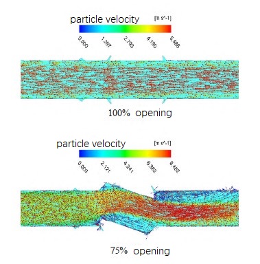
Figure 3 Velocity vector diagram of catalyst particles when the relative opening of wear-resistant ball valve is 100% and 75%.
Conclusion
In order to explore the flow of residual oil medium and the movement of catalyst particles in a high-temperature wear-resistant ball valve, this paper adopts the Euler-Lagrange method to study the flow of residual oil medium containing catalyst particles in a high-temperature wear-resistant ball valve. It is found that when the wear-resistant ball valve is fully opened, the residual oil velocity and particle velocity in the middle of the pipeline are higher than those near the wall. When the opening is small, the residual oil velocity and particle velocity in the valve cavity are very low, and the pressure difference between the front and back of the ball valve is also very large. In the area with high residual oil velocity, the number of particles will be very large; Some particles in the valve core, valve cavity and pipeline will show the characteristics of circulating flow, and the velocity of circulating particles is relatively low.
Physical model and numerical simulation method
1. Physical model
The high-temperature wear-resistant ball valve used in this research is independently developed by the valve designers of Zhejiang Petrochemical Valve Co., Ltd., and its three-dimensional structure is shown in Figure 1. High-temperature wear-resistant ball valve mainly includes a valve body, valve cover, valve stem, bracket, ball and other structures.
Figure 1 Three-dimensional structure diagram of high-temperature wear-resistant ball valve
1. valve stem 2. bracket 3. valve cover 4. ball 5. valve body
By extracting the flow passage inside the high-temperature wear-resistant ball valve, the flow area of residual oil medium inside the wear-resistant ball valve and the pipeline is obtained, and it is used as the calculation domain of this numerical simulation study. Figure 2 shows the schematic diagram of the internal flow passage of the high-temperature wear-resistant ball valve at 50% opening. The internal channel is mainly divided into three parts: the upstream pipeline area, the wear-resistant ball valve cavity area and the downstream pipeline area. Both the upstream pipeline area and the downstream pipeline area extend to a distance of 10 times the diameter of the pipeline, so as to ensure that the residual oil medium and catalyst particles in the calculation can fully develop.
Figure 2 Schematic diagram of the internal flow passage of high-temperature wear-resistant ball valve with 50% opening
2. Numerical simulation method
In this paper, the Euler-Lagrange method is used to calculate the coupling between the residue medium and catalyst particles. The residue flow field is solved by the incompressible Navier-Stokes equation, and the interaction between fluid and particles is added to the momentum equation. The Realizable k-epsilon model is used to solve the turbulent flow. The governing equation of the continuous phase is as follows.
Where V is the velocity of the residual oil medium, ρ is the viscosity of the residual oil medium, P is the pressure, τ is the stress tensor, G is the gravity, and FD is the drag resistance of particles. The motion equation of catalyst is solved by Newton's second law, and the pressure gradient force, virtual mass force, Magnus force and viscous shear force of solid catalyst are not considered. Therefore, the drag resistance and gravity of fluid to particles are mainly used to predict the motion of particles. According to Clift et al.' s research, the motion equation of particles can be written as:
Where
Where Cd is the resistance coefficient, and its formula is given by Morsi and Alexander.
In the process of movement, the particles will collide with the wall and rebound, which will cause the particles to lose some kinetic energy. Therefore, the formula proposed by Grant et al. is used to solve the velocity after particles collide with the wall, and the normal recovery coefficient en and tangential recovery coefficient ET are used to reflect the change of tangential and normal velocity after particles collide with the wall:
In this study, the inlet velocity of residue and catalyst particles is 5 m/s, and the residue medium is Tahe atmospheric residue with a density of 1018.7 kg/m3 and a viscosity of 0.008 262 kg/m-s; The catalyst particles are spherical particles supported by Al2O3, with a diameter of 200μm and a density of 3 650 kg/m3.
Results discussion
1. Verification of grid independence
The computational domain shown in Figure 2 is divided by tetrahedral unstructured grids, and five sets of grids with different numbers are obtained: 800,000, 1 million, 1.2 million, 1.6 million and 2.2 million. When the wear-resistant ball valve is 100% open, five sets of grids are calculated, and the average flow velocity in three calculation domains is obtained. Through comparison, it can be found that when the number of grids exceeds 1.2 million, the correlation between the calculation results and the number of grids is very small. Therefore, this paper uses 2.2 million grids for calculation.
2. Residual oil flow analysis
When the relative opening of the wear-resistant ball valve is 100%, the velocity in the pipeline is relatively uniform. However, due to the viscosity of the residual oil, the wall of the pipeline and the wall of the ball valve has a relatively large viscous force against the flow of the residual oil, which makes the velocity of the residual oil in the middle of the pipeline faster than that on the wall of the pipeline, and the velocity of the residual oil will be lower at the matching positions of the front valve seat and the bonnet, the ball and the front valve seat and the rear valve seat. When the relative opening of the wear-resistant ball valve is 75%, the velocity of residual oil in the middle of the pipeline is still higher than that near the wall, but in the downstream pipeline, the velocity at the bottom of the pipeline is higher than that above the pipeline. In the middle part of the ball of the wear-resistant ball valve, the residual oil velocity in the lower part of the pipeline is lower than that above the pipeline. When the relative opening of the wear-resistant ball valve is 50%, the residual oil has entered the valve cavity and has a very low flow rate in the valve cavity. However, with the decrease of the flow area between the ball valve and the front valve seat, the residual oil forms a high-speed jet when passing through the ball valve, and the high-speed jet hits the upper wall of the valve core pipeline, and sticks to the wall of the valve core pipeline and enters the downstream pipeline, forming a very obvious vortex in the upper half of the downstream pipeline. When the relative opening of the wear-resistant ball valve is 25%, the flow area between the ball and the front valve seat is further reduced, and the throttling effect of the valve is very strong, which makes the high-speed jet in the pipeline more obvious than when the relative opening is 50%, and the high-speed jet will also be close to the wall of the pipeline. When the wear-resistant ball valve is fully open, the relative pressure in the pipeline is relatively small, and the pressure difference between the front and rear positions of the ball is not very large. However, with the decrease of the opening of the wear-resistant ball valve, the pressure in the upstream pipeline gradually increases and the pressure in the downstream pipeline gradually decreases, and the pressure difference between the front and rear of the ball will become very large.
3. Particle distribution near the ball valve
When the relative opening of the wear-resistant ball valve is 100%, the catalyst particles in the residual oil medium can be evenly distributed in the pipeline. With the decrease in the opening of the wear-resistant ball valve, the concentration of catalyst particles in the high-speed area of the ball valve spool pipeline gradually increases. Especially when the relative opening of the wear-resistant ball valve is 50% and 25%, the particles will tend to be near the spool wall under the carrying effect of the high-speed jet of residual oil. It can also be found that there are very few particles in the low-speed area of the spool. When the valve cavity appears, the number of particles near the valve cavity in the low-speed area of the valve core is also relatively small. However, the number of particles will be very large near the valve cavity in the high-speed area of the valve core. The distribution of catalyst particles in the downstream pipeline is quite extreme, that is, the concentration of particles near the sphere at the bottom and upper part of the downstream pipeline is very high.
4. Particle velocity and motion analysis near the wear-resistant ball valve.
Fig. 3 shows the velocity vector diagram of catalyst particles when the relative opening of the wear-resistant ball valve is 100% and 75%. It can be seen from the figure that when the relative opening of the wear-resistant ball valve is 100%, the movement direction of catalyst particles is relatively uniform, mainly along the flow direction of a residual oil medium in the pipeline, and the velocity of catalyst particles in the pipeline is higher than that near the wall. When the relative opening of the wear-resistant ball valve is 75%, it can be inferred from the velocity vector diagram of the particles that the catalyst particles circulate below the spool pipe and above the downstream pipe. The circulating flow of catalyst particles above the downstream pipeline will be more obvious, and the catalyst particles also form a high-speed particle flow at the bottom of the downstream pipeline. Combined with the particle distribution, it is not difficult to speculate that the high concentration distribution at the bottom of the downstream pipeline is caused by the particles following the high-speed jet of residual oil, and the high concentration particles near the sphere at the upper part of the downstream pipeline are caused by the accumulation of particles due to the circular movement of particles. It can also be clearly found that although the number of particles in the valve core pipeline is very small, it can also take the form of circulating flow, and the catalyst particles also have the characteristics of circulating flow in the valve cavity. The velocity of circulating particles in the valve core, valve cavity and the pipeline is relatively low.
Figure 3 Velocity vector diagram of catalyst particles when the relative opening of wear-resistant ball valve is 100% and 75%.
Conclusion
In order to explore the flow of residual oil medium and the movement of catalyst particles in a high-temperature wear-resistant ball valve, this paper adopts the Euler-Lagrange method to study the flow of residual oil medium containing catalyst particles in a high-temperature wear-resistant ball valve. It is found that when the wear-resistant ball valve is fully opened, the residual oil velocity and particle velocity in the middle of the pipeline are higher than those near the wall. When the opening is small, the residual oil velocity and particle velocity in the valve cavity are very low, and the pressure difference between the front and back of the ball valve is also very large. In the area with high residual oil velocity, the number of particles will be very large; Some particles in the valve core, valve cavity and pipeline will show the characteristics of circulating flow, and the velocity of circulating particles is relatively low.
News
Industry News
Back to List
