The cryogenic ball control valve is primarily designed in accordance with GB/T 4213, IEC 60534, and ASME B16.34 standards. Its fire-safe design complies with API 6FA requirements, and the valve packing sealing performance meets ISO 15848-1.2 specifications. The valve is rated for ANSI Class 900 and can withstand a maximum shut-off pressure differential of up to 14.8 MPa, making it ideal for high-pressure applications. The valve body adopts a pilot-balanced design that reduces the thrust required by the actuator by offsetting pressure forces, making it well-suited for high differential pressure conditions. The valve plug and sleeve adopt an equal-percentage flow characteristic, enabling accurate and consistent fluid regulation. Additionally, the high-inlet, low-outlet flow path design utilizes medium pressure to assist in sealing, significantly enhancing the valve’s sealing performance. A schematic diagram of the flow path is shown in Figure 2.
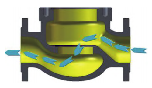
Figure 2: Schematic Diagram of High-Inlet and Low-Outlet Flow Path
Figure 3 shows a sectional view of the cryogenic ball control valve. The valve body features an integrated design that simplifies casting and machining processes, resulting in a compact structure that significantly reduces the risk of leakage. The top-entry design simplifies valve trim replacement, effectively reducing maintenance costs and minimizing system downtime. The integral through-shaft valve stem incorporates a blowout-prevention feature, ensuring safety and operational reliability under high-pressure conditions. The valve plug is designed with an equal-percentage C-characteristic curve, enabling stable, predictable flow control—ideal for applications requiring precise flow regulation. The valve seat leakage rate complies with ANSI/FCI 70.2 standards. Both the valve plug and seat feature a metal-to-metal sealing structure, allowing for easy replacement and incorporating fire-safe gaskets. The valve is equipped with a multi-spring diaphragm pneumatic actuator that ensures smooth and reliable operation. It offers a torque safety factor of 1.5 across the full stroke range, providing sufficient torque to overcome operational resistance under demanding conditions. An intelligent electric valve positioner is integrated, providing high-precision control, rapid response, and automatic monitoring and diagnostics, thereby enhancing overall control accuracy and maintenance efficiency.
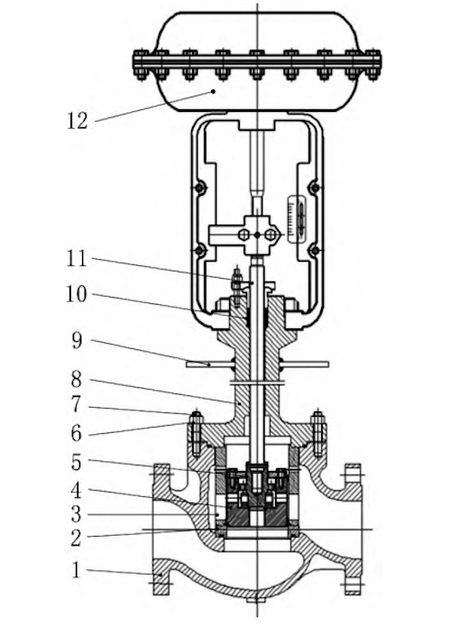
Figure 3: Plane Section View of Cryogenic Ball Control Valve
1. Valve Body 2. Valve Seat 3. Sleeve 4. Large Valve Core 5. Small Valve Core 6. Flange Nut 7. Flange Bolt 8. Upper Valve 9. Drip Tray 10. Packing 11. Valve Stem 12. Pneumatic Actuator
The valve core comprises an independent valve seat, a large valve core, a pilot valve core, and a sleeve (see Figure 4), enabling the ball control valve to achieve precise sealing performance and complex flow control capabilities. The large valve core works in conjunction with the valve seat to effectively block fluid flow when closed, providing the primary sealing function. Meanwhile, the pilot valve core regulates the flow by controlling the movement of the main valve core.
The sleeve is integrated with the valve core, serving as a guide and support to ensure smooth movement of the valve core within the valve seat. The sealing surfaces between the valve core and valve seat feature a metal-to-metal sealing design, offering enhanced wear resistance and corrosion resistance. This design adapts well to high-pressure and low-temperature conditions, ensuring the overall safety and durability of the valve.
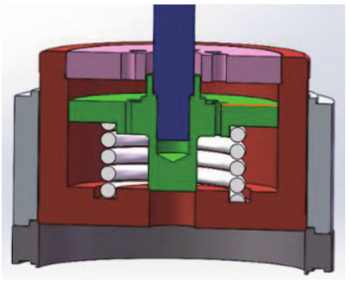
Figure 4 Schematic diagram of sealing structure design
Figure 5 shows an equal percentage characteristic valve cage that achieves a linear change in flow during regulation. Its segmented opening design results in minimal flow variation at small valve openings, while flow increases rapidly at larger openings, creating an exponential relationship between valve opening and flow rate. This design not only improves flow control accuracy and minimizes fluctuations during regulation but also enhances adaptability to various operating conditions, ensuring more stable and precise flow adjustments.
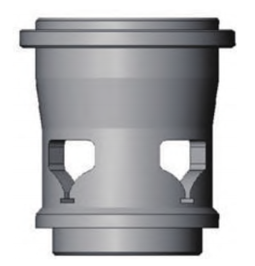
Figure 5 Equal percentage characteristic valve cage
To improve regulation accuracy and response speed under high differential pressure and precision flow control conditions, a pilot structure is integrated as an auxiliary control mechanism to optimize the overall valve performance. The primary functions of the pilot structure are to enhance control accuracy, reduce the torque on the main valve core, balance pressure on both ends of the core, and improve the valve’s dynamic response—thereby increasing its adaptability to complex operating environments. As shown in Figure 6, the spring preload system allows the pilot valve core and the large valve core to operate in coordination. When the valve is closed, the preload maintains firm contact between the valve core and the valve seat, ensuring reliable sealing. During opening, the spring preload maintains dynamic balance, reducing the impact of fluid pressure fluctuations on the valve core and preventing vibration or instability caused by pressure changes. Additionally, the preload minimizes relative sliding between the valve core and valve seat during operation, significantly reducing wear and extending the valve’s service life. It also enhances the valve’s responsiveness to control signals, enabling quicker flow shut-off and adjustment. To further enhance sealing performance and component durability, surface hardening treatments are applied to the valve seat and sleeve. These treatments improve resistance to wear and corrosion, ensuring stable operation during frequent actuation and in harsh media environments. As a result, the hardening process significantly boosts sealing integrity and extends the service life of the sealing components.
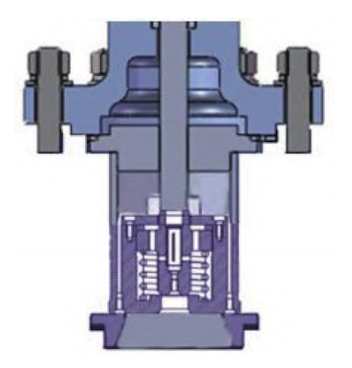
Figure 6: Schematic Diagram of Pilot Balance Trim
The sleeve features symmetrically distributed windows, as shown in Figure 7. As fluid passes through the valve, a counterflow is created inside the sleeve. This counterflow effect helps neutralize the direct impact force of the fluid on the valve core, effectively balancing pressure on both sides. As a result, it reduces valve core offset and vibration caused by pressure differences, thereby improving the valve’s operational stability and flow control accuracy.
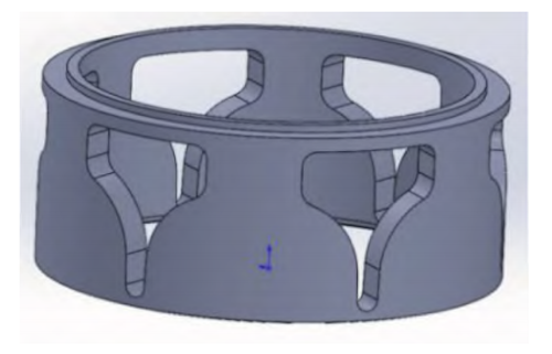
Figure 7: Schematic Diagram of Sleeve Structure
The pilot valve core is fitted with a pressure-balancing plate, as illustrated in Figure 8. This component equalizes the pressure difference across the large valve core during opening, ensuring uniform force distribution on the main valve core for smooth and stable actuation. The balancing plate design greatly reduces the torque needed to open the valve, making operation easier and decreasing the load on the actuator. This is especially advantageous under high-pressure differential conditions, as it helps prevent impact loads and potential valve damage from sudden pressure changes. Furthermore, the upper and lower bearing surfaces of the pilot valve core are nearly identical, ensuring uniform pressure distribution along both axial directions. This design prevents valve core misalignment caused by pressure imbalance and helps extend the valve’s operational lifespan.
This multi-level pressure balancing design not only enhances valve stability and durability in high-pressure cryogenic environments but also improves response speed and control precision, making it ideal for demanding flow regulation applications.
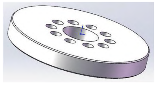
Figure 8: Schematic Diagram of Pressure Balancing Plate
The cryogenic ball control valve regulates fluid flow by actuating the valve core through the valve stem, altering its relative position to the sleeve window. This movement adjusts the flow area and thereby controls the flow rate. The flow regulation principle is illustrated in Figure 9. Precise regulation relies on the accurate alignment between the valve core and the sleeve window. As the valve core gradually opens or closes, the flow area changes accordingly, allowing the flow rate to increase or decrease. The valve is typically designed with equal-percentage flow characteristics, meaning that each incremental change in the valve core’s rotation angle results in a proportional percentage change in flow rate. This ensures consistent flow modulation under both low-flow and high-flow conditions, making the valve ideal for applications requiring high-precision flow control. The internal contour of the valve seat is precisely matched to the outer surface of the valve core. When the valve core is fully aligned with the valve seat, the valve achieves its maximum flow capacity. This design not only facilitates smooth, linear flow regulation but also ensures stable valve core movement throughout the control range, thereby enhancing both control accuracy and the valve’s adjustable range.
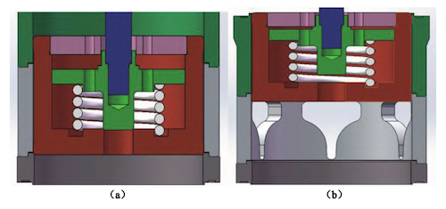
Figure 9: Schematic Diagram of Ball Valve Regulation
(a) Fully Closed (b) Fully Open
The flow coefficient curve (Cv curve) is a key parameter for evaluating control valve performance, illustrating how the valve’s flow coefficient varies with different valve openings. Although expressed without units, the Cv (flow coefficient) quantifies a valve’s capacity to pass fluid under a specified pressure differential. By analyzing the Cv curve, engineers can select the optimal valve size to ensure the system meets its flow requirements across varying operating conditions. The Cv value quantifies the volume of water, in U.S. gallons per minute, that flows through the valve with a pressure drop of 1 psi. The shape of the Cv curve directly affects the valve’s flow response and control performance. Depending on process requirements, the Cv curve may exhibit a linear or nonlinear trend—such as an equal percentage characteristic—to provide the desired flow modulation behavior. When selecting a cryogenic ball valve, it is essential to consider several factors, including the valve’s control range, stability, flow capacity, pressure drop characteristics, as well as its operating temperature and pressure limits. An in-depth analysis of the Cv curve enables evaluation of flow variation across different valve openings, ensuring accurate and stable flow control in a wide range of industrial applications. For example, Figure 10 shows the Cv curve of a cryogenic ball control valve with a nominal diameter of NPS 4. This valve is rated for ANSI Class 900 pressure, has an operating temperature range from –196°C to 150°C, and a rated Cv value of 170. The curve exhibits a classic equal-percentage flow characteristic: flow increases gradually at small openings and accelerates rapidly at larger openings. This behavior is ideal for applications requiring high-precision flow regulation. As illustrated in Figure 10, when the valve opening reaches 75.29%, the corresponding Cv value is 90.24. This demonstrates that the valve provides excellent flow regulation accuracy and rapid responsiveness at this position, fully meeting the system’s performance requirements.
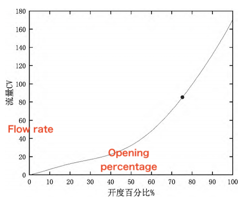
Figure 10: Cv Curve of NPS 4 Cryogenic Ball Control Valve
Material verification is a critical step in ensuring the reliability, safety, and low-temperature performance of cryogenic valve components. The inspection process begins with dimensional and visual examinations, using precision measuring instruments to confirm that all components meet the specified geometric and surface quality standards. Next, spectral analysis is conducted to determine the chemical composition of the materials, verifying their compliance with design specifications. Mechanical properties are evaluated through tensile and impact testing at cryogenic temperatures to ensure the material retains sufficient strength and toughness under extreme service conditions. To assess internal quality, radiographic inspection of the valve body is carried out by a certified third-party organization to detect any hidden internal defects. Dye penetrant testing is performed on all pressure-bearing components to detect surface-level discontinuities such as microcracks, thereby ensuring structural integrity and reliable sealing performance. Additionally, ultrasonic thickness gauges and specialized measuring instruments are used to verify that the shell thickness meets design pressure requirements and remains within safe operational limits. Finally, hardness testing is performed to assess the material’s resistance to deformation, confirming its capability to operate reliably under mechanical stress. The material verification process involves a comprehensive assessment of dimensions, chemical composition, mechanical properties, surface integrity, and hardness, ensuring that all materials meet the stringent quality standards required for LNG ultra-low-temperature control valves.
Performance testing of finished cryogenic ball control valves is conducted in strict accordance with the Technical Specifications for Control Valves to ensure stability and reliability under actual operating conditions. The following test procedures and standards are implemented to ensure a comprehensive assessment of product quality:
Appearance and Dimensional Inspection
Each valve undergoes visual and dimensional inspections to verify compliance with the MSS SP-55 standard. This step detects surface defects, unacceptable roughness, or manufacturing flaws, ensuring the product meets fundamental standards for structural integrity and workmanship.
Ambient Temperature Performance Test
Key operational parameters, including actuation performance and flow control accuracy, are evaluated at room temperature. This verifies the valve’s sensitivity and response speed under standard conditions, ensuring reliable operation during typical service.
Cryogenic Performance and Actuation Test
To meet the stringent demands of LNG and ultra-low-temperature applications, the valve undergoes testing in a simulated cryogenic environment. This test assesses the valve’s operational smoothness and sealing performance at low temperatures, verifying its ability to open and close smoothly while maintaining a tight shutoff under liquefied natural gas conditions.
Ambient Temperature Recovery Test
After completion of the cryogenic test, the valve is returned to room temperature for recovery evaluation. Observing the valve’s recovery behavior provides insight into the material and structural adaptability to extreme temperature fluctuations. This test verifies the valve’s fatigue resistance, structural stability, and long-term durability.
External Leakage Test
The valve is tested for external leakage in accordance with ANSI FCI 70.2 and ISO 15848-2 standards. This ensures the absence of leakage from the body, bonnet, or seals during operation, thereby meeting environmental safety standards and ensuring long-term sealing reliability in high-pressure cryogenic applications.
Coating Dry Film Thickness Test
To enhance corrosion resistance, the valve’s paint coating undergoes inspection for dry film thickness to ensure uniformity and compliance with specified standards. This test helps safeguard the valve’s internal and external components against corrosion, thereby extending its service life in harsh environments. This comprehensive series of performance tests—including visual inspection, thermal adaptability, sealing integrity, and corrosion protection—ensures that the cryogenic ball control valve meets all necessary quality and performance standards for safe and stable operation in LNG and other demanding low-temperature environments.
Comprehensive quality control and assurance measures are rigorously applied at every stage of the manufacturing process for cryogenic ball control valves. These procedures are essential to ensure high product reliability and to meet the stringent performance requirements of cryogenic environments, such as those encountered in LNG systems. All incoming materials and components must undergo a thorough incoming inspection, including chemical composition analysis and mechanical property testing, to verify compliance with engineering specifications. Prior to machining, critical components—such as valve stems and sealing elements—undergo heat treatment and cryogenic treatment to enhance their strength, dimensional stability, and resistance to low temperatures. During the manufacturing stage, both rough and precision machining processes—such as turning, milling, grinding, boring, and drilling—are meticulously performed. Key components, such as valve bodies and valve stems, undergo additional surface treatments and cryogenic conditioning to improve wear resistance and performance in cryogenic environments. Each machining step is accompanied by first-article inspections and in-process quality checks to verify that all dimensions and tolerances conform to design specifications. Particular attention is given to grinding the sealing surfaces, with grinding parameters strictly controlled and continuously monitored in real time. This ensures that the final sealing surfaces achieve the required leak-tightness and performance standards. Once assembled, the finished valve undergoes rigorous pressure testing and non-destructive testing (NDT) to verify its sealing integrity and pressure resistance under simulated operating conditions. These tests are essential to ensuring operational safety in high-pressure, ultra-low-temperature applications. Before the product leaves the factory, a final coating process is applied, followed by measurement of the dry film thickness to ensure consistent corrosion protection. This additional protection helps extend the valve’s service life in harsh operating environments. Any non-conforming products undergo rework or corrective actions to ensure the final cryogenic ball control valve fully complies with all technical specifications and international quality standards.
This study presents the design of a cryogenic spherical control valve specifically engineered for use in LNG applications. The integrated valve body design significantly reduces leakage risk, while the top-mounted configuration simplifies maintenance procedures and minimizes downtime. The incorporation of a long-necked bonnet and a specialized sealing structure ensures excellent corrosion resistance, sealing integrity, and mechanical performance, even under extreme cryogenic conditions. Furthermore, this paper addresses the key technical challenges encountered during the design process and proposes targeted engineering solutions, including:
Sealing Effectiveness under High Pressure Differential:
A high-inlet, low-outlet flow path design leverages the medium’s pressure differential to achieve self-sealing. This approach reduces the external force on the sealing surface, enhances sealing performance, and lowers the risk of leakage.
Valve Actuation Difficulty under High Pressure Differential:
A pilot sleeve structure is incorporated to optimize fluid flow guidance and maintain internal pressure balance, thereby reducing actuation torque under high pressure differentials. This design reduces the required opening thrust, minimizes actuator load, and enhances operational efficiency during valve actuation.
Wear Caused by Unbalanced Stem Forces:
The valve stem and pilot valve core are designed to maintain balanced pressure distribution on both the upper and lower sides of the stem, minimizing uneven wear. This reduces unbalanced torque, minimizes wear on the stem and guiding components, and extends the valve’s service life. In summary, the cryogenic spherical regulating valve designed in this work demonstrates high reliability, precise flow control, and robust sealing performance—making it ideally suited for the demanding low-temperature conditions of LNG service.