Posted Dec 10, 2021
Analyses of the Control Valves Noise
1. Aerodynamic noise
Aerodynamic noise is caused by gas or steam flowing through the orifice. The noise of control valves encountered in the industry is mostly aerodynamic noise. Gas and steam are all compressible fluids. Generally speaking, the flow rate of compressible fluid is higher than that of incompressible fluid. When the gas velocity is lower than the sound velocity, the noise is caused by strong turbulence. When the velocity of the gas is greater than the velocity of sound, shock waves are generated in the fluid, so the noise increases sharply. Comparing all kinds of noises, the noise caused by compressible fluid flowing through the control valve is the most serious.
2. Hydrodynamic noise
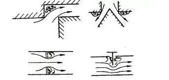
Hydrodynamic noise is caused by liquid flowing through the throttle hole of the control valve. There are various structures of control valves, and typical throttling forms are shown in Figure 1. Although the structural forms of various throttles are different, they all have a throttling effect on the liquid. When the liquid passes through the orifice, due to the sharp change of the orifice area, the flow area is reduced, and the flow rate is increased while the pressure is decreased, which easily leads to blocking flow, flash evaporation and cavitation, all of which are the causes of noise.
When the pressure difference between the front and back of the valve throttle is small, the noise of the throttle is extremely small and the flowing sound is not loud, so it is unnecessary to consider the noise problem. If the pressure difference is large, the fluid flowing through the control valve begins the flash distillation, and the flowing fluid becomes a mixture of gas and liquid with bubbles. The deceleration and expansion of the two-phase fluid naturally causes noise. Moreover, because of the sharp change of the shut-off section near the electric control valve, the flow velocity is uneven in the high-speed jet, resulting in a vortex shedding sound.
When cavitation occurs, bubbles burst and powerful energy not only produces destructive power but also makes noise, sometimes with a frequency as high as 10000Hz. The more and larger bubbles are, the more serious the noise is.
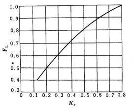
When selecting the control valve, in order to avoid hydrodynamic noise, the key is to find the valve pressure drop ΔPC at the beginning of cavitation and ensure that the valve pressure drop is less than ΔPC. Therefore, a concept of initial cavitation coefficient KC is introduced.

The value of KC is obtained by experiment, and it can also be determined according to the pressure coefficient FL of liquid. Figure 2 shows the relationship between FL and KC.
3. Vortex shedding noise
Among various noise types, there is a kind of vortex shedding noise, which is very easy to generate when compressible fluid flows over the surface of an object. When the fluid particles flow to the leading edge of a streamlined cylinder, the fluid is blocked, and the pressure rises from the state of free flow to another state due to the conversion of the kinetic energy of the fluid. After the fluid bypasses the cylinder and forms a boundary layer, it continues to flow. When Reynolds number Re is different, the fluid flow of control valves is different.
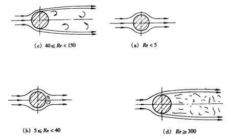
It can be seen from fig. 3 that when Re < 5, the fluid does not leave the cylinder, seeing diagram (a). When 5 ≤ Re < 40, a pair of the stable vortex, seeing diagrams (B), are formed close to the back of the cylinder in the wake. When 40 ≤ Re < 150, the symmetric vortex breaks, and stable, asymmetric, regularly arranged vortex arrays with opposite rotation directions appear in the wake, which periodically leaves the cylinder (C). When Re > 150, the vortex array is no longer stable. When Re≥300, the whole wake region has become turbulent (D).
The Reynolds number Re of an incompressible fluid is generally very large. In this case, the boundary layer can't surround the back of the cylinder but is separated from both sides of the cylinder surface, forming two shear layers extending to the tail in the flow. These two shear layers form the boundary of the wake because the inner layer of the control valve moves much slower than the outermost layer. Therefore, these free shear layers tend to roll into a discontinuous swirling vortex, which forms a vortex flow in the wake, and the vortex flow interacts with the cylinder to induce vibration. When the vortex alternately falls off from both sides of the cylinder, it also stimulates the periodic pulse force of the cylinder. This force causes the elastic cylinder to vibrate and sound like the wind. When the wind blows through the electric wire, you can hear the sound of the wind, which is the phenomenon of vortex shedding. However, when the frequency of vortex shedding is close to or the same as the natural frequency of cylinder, vibration increases, resonance occurs and noise increases. When Re > 3× 10⁵, the vortex shedding is very messy and forms a wide frequency band.
If the part has a non-circular cross-section, the above phenomena and conclusions are also applicable.
In a word, when the compressible fluid flows through the pneumatic regulating valve, it may reach or exceed the sound speed at the minimum throttle section, which will form messy fluid such as shock wave, jet flow and vortex flow. This fluid will be converted into heat energy downstream of the throttle hole. At the same time, it generates aerodynamic noise, which will be transmitted everywhere along the downstream pipeline. In severe cases, the pipeline system will be damaged due to excessive vibration.
Aerodynamic noise is caused by gas or steam flowing through the orifice. The noise of control valves encountered in the industry is mostly aerodynamic noise. Gas and steam are all compressible fluids. Generally speaking, the flow rate of compressible fluid is higher than that of incompressible fluid. When the gas velocity is lower than the sound velocity, the noise is caused by strong turbulence. When the velocity of the gas is greater than the velocity of sound, shock waves are generated in the fluid, so the noise increases sharply. Comparing all kinds of noises, the noise caused by compressible fluid flowing through the control valve is the most serious.
2. Hydrodynamic noise
Hydrodynamic noise is caused by liquid flowing through the throttle hole of the control valve. There are various structures of control valves, and typical throttling forms are shown in Figure 1. Although the structural forms of various throttles are different, they all have a throttling effect on the liquid. When the liquid passes through the orifice, due to the sharp change of the orifice area, the flow area is reduced, and the flow rate is increased while the pressure is decreased, which easily leads to blocking flow, flash evaporation and cavitation, all of which are the causes of noise.
When the pressure difference between the front and back of the valve throttle is small, the noise of the throttle is extremely small and the flowing sound is not loud, so it is unnecessary to consider the noise problem. If the pressure difference is large, the fluid flowing through the control valve begins the flash distillation, and the flowing fluid becomes a mixture of gas and liquid with bubbles. The deceleration and expansion of the two-phase fluid naturally causes noise. Moreover, because of the sharp change of the shut-off section near the electric control valve, the flow velocity is uneven in the high-speed jet, resulting in a vortex shedding sound.
When cavitation occurs, bubbles burst and powerful energy not only produces destructive power but also makes noise, sometimes with a frequency as high as 10000Hz. The more and larger bubbles are, the more serious the noise is.
When selecting the control valve, in order to avoid hydrodynamic noise, the key is to find the valve pressure drop ΔPC at the beginning of cavitation and ensure that the valve pressure drop is less than ΔPC. Therefore, a concept of initial cavitation coefficient KC is introduced.
The value of KC is obtained by experiment, and it can also be determined according to the pressure coefficient FL of liquid. Figure 2 shows the relationship between FL and KC.
3. Vortex shedding noise
Among various noise types, there is a kind of vortex shedding noise, which is very easy to generate when compressible fluid flows over the surface of an object. When the fluid particles flow to the leading edge of a streamlined cylinder, the fluid is blocked, and the pressure rises from the state of free flow to another state due to the conversion of the kinetic energy of the fluid. After the fluid bypasses the cylinder and forms a boundary layer, it continues to flow. When Reynolds number Re is different, the fluid flow of control valves is different.
It can be seen from fig. 3 that when Re < 5, the fluid does not leave the cylinder, seeing diagram (a). When 5 ≤ Re < 40, a pair of the stable vortex, seeing diagrams (B), are formed close to the back of the cylinder in the wake. When 40 ≤ Re < 150, the symmetric vortex breaks, and stable, asymmetric, regularly arranged vortex arrays with opposite rotation directions appear in the wake, which periodically leaves the cylinder (C). When Re > 150, the vortex array is no longer stable. When Re≥300, the whole wake region has become turbulent (D).
The Reynolds number Re of an incompressible fluid is generally very large. In this case, the boundary layer can't surround the back of the cylinder but is separated from both sides of the cylinder surface, forming two shear layers extending to the tail in the flow. These two shear layers form the boundary of the wake because the inner layer of the control valve moves much slower than the outermost layer. Therefore, these free shear layers tend to roll into a discontinuous swirling vortex, which forms a vortex flow in the wake, and the vortex flow interacts with the cylinder to induce vibration. When the vortex alternately falls off from both sides of the cylinder, it also stimulates the periodic pulse force of the cylinder. This force causes the elastic cylinder to vibrate and sound like the wind. When the wind blows through the electric wire, you can hear the sound of the wind, which is the phenomenon of vortex shedding. However, when the frequency of vortex shedding is close to or the same as the natural frequency of cylinder, vibration increases, resonance occurs and noise increases. When Re > 3× 10⁵, the vortex shedding is very messy and forms a wide frequency band.
If the part has a non-circular cross-section, the above phenomena and conclusions are also applicable.
In a word, when the compressible fluid flows through the pneumatic regulating valve, it may reach or exceed the sound speed at the minimum throttle section, which will form messy fluid such as shock wave, jet flow and vortex flow. This fluid will be converted into heat energy downstream of the throttle hole. At the same time, it generates aerodynamic noise, which will be transmitted everywhere along the downstream pipeline. In severe cases, the pipeline system will be damaged due to excessive vibration.
