Posted May 31, 2022
Fault Detection Technology of Valves
Valve is a common equipment in industrial manufacturing, which is mainly used to control the flow and cutoff of the medium. Affected by the environment, medium impact, corrosion, high-temperature creep and other factors, valves are prone to failure. Taking nuclear power valves as an example, gate valves and solenoid valves have the greatest failure probability, followed by check valves, regulating valves and pressure reducing valves. If the valve fails and can't be found in time and handled accurately, it will lay a hidden danger for industrial production and personnel safety. With the rapid development of information technology, valve fault detection technology can timely and accurately grasp the running state of the valve, which provides an important way for valve maintenance and troubleshooting. However, at present, there are many methods of valve fault detection, with different application conditions and no uniform standard. Therefore, the summary of valve fault detection technology and its research progress has very important practical significance for stabilizing industrial production, reducing costs and improving resource utilization.
Failure Mode and Cause Analysis
The failure mode and cause analysis of the valve is the basis to ensure the reasonable design and normal operation of the valve. The main failure modes and causes are shown in Table 1.
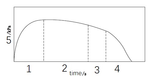
Figure 1 Principle of pressure drop method (1. Inflating 2. Holding 3. Testing 4. Exhaust 5. Pressure)
Table 1 Main failure modes and causes of valves
Leakage: ① Unreasonable design. There is no reliable design system combined with the operating environment, and there is no reasonable design for sealing surface, packing, sealing ring, material roughness and other factors.
② Unreasonable structure. The valve structure size, sealing interval, sealing specific pressure, etc. are not reasonably designed.
③ Unreasonable materials. The mechanical properties, corrosion resistance and composition of the sealing materials were not reasonably selected.
Rupture of valve body: ① Improper selection of valve body materials or defects of materials, such as sand holes, air bubbles, shrinkage cavities, etc.
② External environmental factors, such as low temperature, high temperature, high pressure, etc., cause the valve body to creep, fatigue, impact and other phenomena resulting in the valve body cracking.
③ Strong vibration, resonance or violent disassembly make the valve bear uneven stress and crack. During the working process, due to the impact of the medium, the crack is prolonged and the valve body is damaged.
Stuck: ① The valve is stuck due to deformation caused by materials, stress superposition and other factors, or physical reasons such as excessive and tight packing.
② The valve is stuck due to pollution caused by the working environment or chemical corrosion and other reasons.
Vibration and noise: ① Mechanical vibration. The unreasonable layout of the number and spacing of process pipes, elbows and valves lead to vibration or pressure pulsation of medium fluid in the pipes.
② The external environment resonates with the medium fluid, which causes the valve to vibrate.
③ Cavitation vibration.
④ Hydrodynamic vibration.
Although many scholars have analyzed and improved the main failure modes of valves from the aspects of material, design, structure and operation, there are still some problems.
(1) Most of the analysis improvements are aimed at specific situations. How to carry out quantitative analysis from qualitative analysis and obtain widely applicable methods needs further study.
(2) In the actual work of the valve, the flow of medium fluid is complex, and many factors such as fluid impact, corrosion and thermal stress may be superimposed together. In the simulation, some conditions will be ignored or idealized, which is unfavorable to the valve design and reliability analysis.
(3) After the valve fails, it is of great significance to use the fault detection technology to improve the accurate identification of the occurrence and development of the valve failure, to ensure the safe operation of the processing system and to study the reliability of the valve.
Detection Technology
The valve fault detection technology is to use sensors to monitor the running state of the valve and obtain the working signal of the valve. By comparing the historical state information, the running state of the valve can be predicted and fed back. Extract and process abnormal signals, analyze the causes and mechanisms of valve failures, determine the types and levels of valve failures, and decide whether to carry out necessary shutdown and maintenance. Timely and accurate acquisition of abnormal signals of valves is a prerequisite for valve failure detection. According to the failure forms and causes in Table 1, signal acquisition and sensing are divided into detection methods for valve leakage and detection methods for valve stuck and broken failure forms.
1. Detection method of valve leakage
The earliest methods of valve leakage detection technology are pressure detection, vacuum detection and bubble detection. This kind of method requires the valve to stop working, and the valve should be disassembled from the pipe fittings for testing. This kind of method is easy to cause valve damage, which belongs to off-line detection and has low detection efficiency. In order to realize online nondestructive testing of valve leakage in the industrial field, experts and scholars have carried out a lot of experimental studies, including pressure drop method, vibration method, thermal infrared method, ultrasonic testing method, and optical fiber leakage method and acoustic emission testing method.
(1) pressure drop method
The pressure drop method is to lead clean and dry compressed air to the sealed detection valve and install pressure sensors upstream and downstream respectively. Through the processes of inflation, pressure keeping, detection and exhaust, the changes in the pressure in the measured valve are monitored and recorded (Figure 1). If the upstream and downstream pressures of the valve have obvious changes, the valve has leakage. To reflect the leakage situation more intuitively, the pressure change can be converted into the leakage amount (Figure 2).
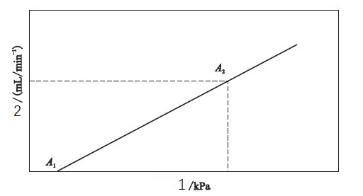
Figure 2 Conversion curve of pressure drop and leakage rate (1. Pressure drop 2. Leakage rate)
The pressure drop method has the advantages of simple operation, low cost and easy realization of automatic detection, but it is greatly affected by temperature, and the detection effect of tiny leakage is not ideal. The pressure drop method is divided into the direct pressure method and the differential pressure method. The direct pressure method directly detects the change in the internal pressure of the measured valve, while the differential pressure method measures the pressure difference between the measured valve and the standard valve. Compared with the direct pressure method, the differential pressure method can reduce the influence of temperature change on pressure measurement. Xiao Xiangzheng has studied the influence of temperature on the differential pressure method. The experiment shows that when the temperature changes below 1℃, the influence on pressure measurement can be ignored, otherwise, the pressure measurement should be corrected according to the correction formula of temperature and the effective volume formula obtained from the experiment. Qianjie used the direct pressure method and differential pressure method to test the airtightness of PE pipe valve, established a mathematical model and test device, investigated the influence of temperature and other factors on pressure measurement through simulation test, and adjusted the leakage parameters. The minimum detection leakage rate was 8.5× 10⁻⁴ Pa m3/s, which met the experimental expectation.
(2) Thermal infrared method
The infrared method refers to the use of detection instruments to capture the surface temperature distribution of objects that cannot be directly seen by human eyes, capture the temperature difference between the upstream and downstream of the valve, and form infrared images, so as to judge whether the valve leaks or not. The infrared method is mainly divided into active detection (Figure 3) and passive detection (Figure 4). It has the advantages of high detection sensitivity, convenience, quick response, etc., but it is only suitable for cases with obvious temperature differences. Guan Shitao et al. installed a temperature transmitter beside the valve to transmit the temperature signal to the gas valve leakage detection system based on ZigBee technology, thus realizing the detection of valve leakage.
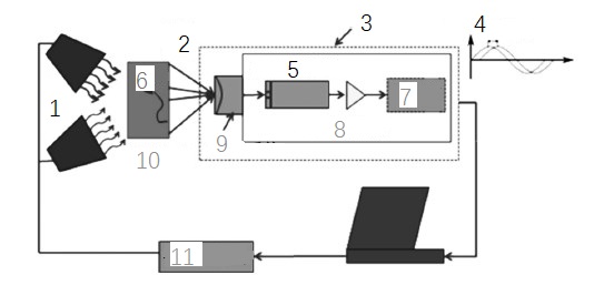
Figure 3 Active detection (1. excitation source 2. infrared radiation 3. infrared thermal imager 4. PC terminal 5. infrared detector 6. defect 7. display 8. signal processor 9. optical system 10. measured object 11. signal generator)
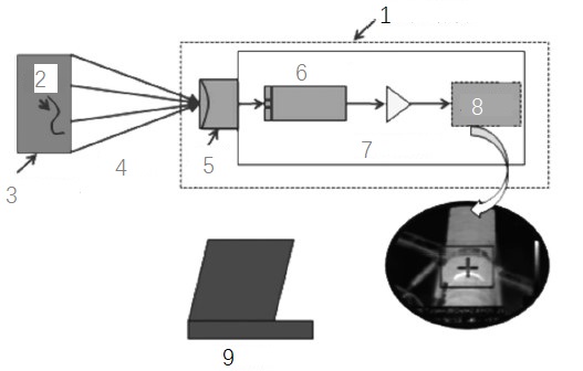
Figure 4 Passive detection (1. infrared thermal imager 2. defect 3. measured object 4. infrared radiation 5. optical system 6. infrared detector 7. signal processor 8. display 9. PC terminal)
(3) Vibration method
The vibration method uses the sensor to capture the vibration signal of the valve pipeline, and through the processing of the vibration signal, analyzes its time, frequency, acceleration and other characteristics, obtains the modal parameters, and then compares them with the normal modal values to determine whether the valve leaks. Thompson et al. have done a lot of experimental research on gas valves by using the vibration method. The results show that this method is simple to operate and has high detection sensitivity. The vibration method can detect valve leakage with low-pressure drop and small leakage rate in a laboratory environment. The detection result is not affected by valve type, pipe material and thickness, but only related to the pipe diameter. However, its disadvantage is that it is sensitive to industrial noise. Some scholars have studied this and found that the vibration method can effectively capture the noise between 0 and 0-20 kHz, which will bring errors and uncertainties to valve leakage detection.
(4) Optical fiber detection method
The optical fiber detection method is mainly applicable to underground pipelines and valves. According to the principle of the Joule-Thomson effect, when the pipeline leaks, the temperature near the leakage source will also decrease. By monitoring the local temperature change, the valve leakage can be monitored and located. The optical fiber method has high detection efficiency and positioning accuracy, but when the leakage amount is small, the temperature change near the leakage source is small, and the detection sensitivity of the optical fiber sensor is required to be high, so the cost is relatively high. Close to the valve of the optical fiber pipeline, the detection optical fiber and the leakage point cannot be located at both ends of the pipeline (Figure 5), so three optical fibers should be buried and evenly distributed around the pipeline (Figure 6).
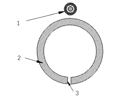
Fig. 5 The detection optical fiber and the leakage point are at both ends of the pipeline (1. optical fiber 2. pipeline 3. leakage point)
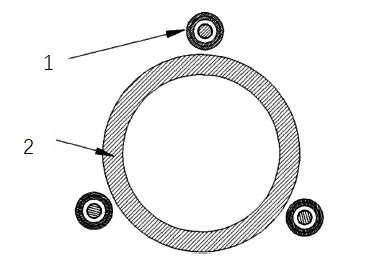
Fig. 6 Three optical fibers are evenly distributed around the pipeline (1. optical fiber 2. Pipeline)
(5) Acoustic emission detection method
Acoustic emission testing is a widely used nondestructive testing technology at present. Its principle is to capture the continuous high-frequency fluctuation signal generated by the valve leakage medium on the valve body and realize the valve leakage testing according to the law that the leakage acoustic emission characteristic is proportional to the leakage rate. To filter out environmental noise, the filter band can be set to 100-400 kHz. Gao Qianxia used acoustic emission technology to detect the leakage of valves under different conditions, obtained three formulas for calculating the leakage rate based on acoustic emission characteristic values, and realized the quantitative diagnosis of valve leakage faults. The advantages of acoustic emission detection are as follows.
① There is no need to disassemble the detected equipment, which will not cause damage to the equipment, and the detection method is simple and convenient.
② There is no need to approach dangerous valves such as high temperature and high pressure.
③ The detection is fast, real, intuitive and quantitative. The acoustic emission detection method also has some limitations, because its central frequency is generally around 150 kHz, and its sampling frequency is as high as 1 MHz, which not only requires fast processing speed and large memory of hardware equipment, but also requires high signal analysis and processing, feature extraction and diagnostic modeling. The principle of acoustic emission detection is shown in Figure 7.
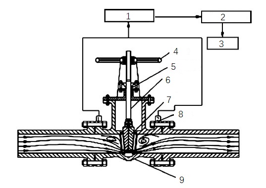
Fig. 7 Principle of acoustic emission detection (1. preamplifier 2. signal acquisition card 3. computer 4. handwheel 5. packing 6. valve stem 7. gate 8. flange 9. valve body)
(6) Ultrasonic detection method
When the valve leaks, the medium flows out from the leak point. When the leak hole is small and the pressure is high, the sound wave emitted is higher than 20 kHz. Although the human ear can't hear it, it can be captured by the ultrasonic sensor. Using the characteristic of directional propagation of ultrasonic waves and inverse ratio to distance, the leakage position can be found quickly. Considering the influence factors of environmental noise, by comparing the frequency spectrum distribution of leakage sound and noise, it can be found that if the center frequency of the ultrasonic signal generated by valve leakage is 40 kHz, the accuracy of the ultrasonic signal can be guaranteed and the surrounding environmental noise can be filtered out. The ultrasonic detection method also has its limitations. First, the pressure must be greater than 0.34 MPa or higher to ensure that the sound frequency emitted by the leak reaches the detectable range; Second, it can't accurately identify the leaked liquid, which is more suitable for gas or steam media. Wang Chao [6] suggested that pressure and temperature can be used as auxiliary means to make up for the defects of ultrasonic testing and better detect the leakage of valves. The frequency spectrum distribution of valve leakage sound and noise is shown in Figure 8.
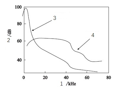
Fig. 8 Spectrum distribution of leakage sound and noise (1. frequency 2. sound pressure level 3. background noise 4. leakage sound)
2. Detection methods of valve sticking, rupture and other faults
(1) Install the positioner, which is mainly aimed at the regulating valve, and monitor the dynamic characteristics of the valve by detecting the valve stem displacement, input signal, unbalance force, friction force and other parameters, and reducing the equivalent time of the secondary circuit. Judge the state of the valve according to the change of parameters.
(2) Use a strain flower or strain gauge to measure the stress, torque and other information of the measured part. Numerical simulation and strain tests are carried out on the stress of the valve shell. The shell surface is not unidirectional stress, so the strain gauge should be used for the test, and the results are in good agreement. A clamp thrust sensor can be used to measure the thrust of the valve stem, and an acceleration sensor, dynamic strain gauge and pressure sensor installed at the end of the valve can realize the real-time measurement of valve data.
(3) Combining infrared technology with ultrasonic technology, cracks in important parts such as the valve body can be detected. Besides the above-mentioned common detection methods, there are water detection methods, halogen methods, helium mass spectrometry, etc., but they are not suitable for large-scale industrial production because of errors and easy pollution. The detection accuracy of different detection methods is shown in Table 2.
Table 2 Detection accuracy of different detection methods
Pressure drop method: detection accuracy/(pa m3/s): 10-5 - 10-3
Ultrasonic method: detection accuracy/(pa m3/s): 10-4 - 10-3
Infrared method: detection accuracy/(pa m3/s): 10-7
Ammonia gas method: detection accuracy/(pa m3/s): 10-8
Water detection method: detection accuracy/(pa m3/s): 10-6 - 10-5
Helium mass spectrometry: detection accuracy/(pa m3/s): 10-9
Halogen method: detection accuracy/(pa m3/s): 10-7 - 10-6
Conclusion
The research and development of valve fault detection technology are particularly important for industrial production. By discussing different detection methods and summarizing their advantages and disadvantages, it provides convenient conditions for experimental research and necessary technical support for the reliability of valves and the smooth progress of industrial production. Due to the influence of using conditions and testing environment, various methods should be considered to improve the testing accuracy. For noise and other interference signals, corresponding treatment measures should be taken to prevent adverse effects on the test results. We should continue to study valve detection methods in-depth, expand its application scope, improve detection efficiency and reduce cost.
Failure Mode and Cause Analysis
The failure mode and cause analysis of the valve is the basis to ensure the reasonable design and normal operation of the valve. The main failure modes and causes are shown in Table 1.
Figure 1 Principle of pressure drop method (1. Inflating 2. Holding 3. Testing 4. Exhaust 5. Pressure)
Table 1 Main failure modes and causes of valves
Leakage: ① Unreasonable design. There is no reliable design system combined with the operating environment, and there is no reasonable design for sealing surface, packing, sealing ring, material roughness and other factors.
② Unreasonable structure. The valve structure size, sealing interval, sealing specific pressure, etc. are not reasonably designed.
③ Unreasonable materials. The mechanical properties, corrosion resistance and composition of the sealing materials were not reasonably selected.
Rupture of valve body: ① Improper selection of valve body materials or defects of materials, such as sand holes, air bubbles, shrinkage cavities, etc.
② External environmental factors, such as low temperature, high temperature, high pressure, etc., cause the valve body to creep, fatigue, impact and other phenomena resulting in the valve body cracking.
③ Strong vibration, resonance or violent disassembly make the valve bear uneven stress and crack. During the working process, due to the impact of the medium, the crack is prolonged and the valve body is damaged.
Stuck: ① The valve is stuck due to deformation caused by materials, stress superposition and other factors, or physical reasons such as excessive and tight packing.
② The valve is stuck due to pollution caused by the working environment or chemical corrosion and other reasons.
Vibration and noise: ① Mechanical vibration. The unreasonable layout of the number and spacing of process pipes, elbows and valves lead to vibration or pressure pulsation of medium fluid in the pipes.
② The external environment resonates with the medium fluid, which causes the valve to vibrate.
③ Cavitation vibration.
④ Hydrodynamic vibration.
Although many scholars have analyzed and improved the main failure modes of valves from the aspects of material, design, structure and operation, there are still some problems.
(1) Most of the analysis improvements are aimed at specific situations. How to carry out quantitative analysis from qualitative analysis and obtain widely applicable methods needs further study.
(2) In the actual work of the valve, the flow of medium fluid is complex, and many factors such as fluid impact, corrosion and thermal stress may be superimposed together. In the simulation, some conditions will be ignored or idealized, which is unfavorable to the valve design and reliability analysis.
(3) After the valve fails, it is of great significance to use the fault detection technology to improve the accurate identification of the occurrence and development of the valve failure, to ensure the safe operation of the processing system and to study the reliability of the valve.
Detection Technology
The valve fault detection technology is to use sensors to monitor the running state of the valve and obtain the working signal of the valve. By comparing the historical state information, the running state of the valve can be predicted and fed back. Extract and process abnormal signals, analyze the causes and mechanisms of valve failures, determine the types and levels of valve failures, and decide whether to carry out necessary shutdown and maintenance. Timely and accurate acquisition of abnormal signals of valves is a prerequisite for valve failure detection. According to the failure forms and causes in Table 1, signal acquisition and sensing are divided into detection methods for valve leakage and detection methods for valve stuck and broken failure forms.
1. Detection method of valve leakage
The earliest methods of valve leakage detection technology are pressure detection, vacuum detection and bubble detection. This kind of method requires the valve to stop working, and the valve should be disassembled from the pipe fittings for testing. This kind of method is easy to cause valve damage, which belongs to off-line detection and has low detection efficiency. In order to realize online nondestructive testing of valve leakage in the industrial field, experts and scholars have carried out a lot of experimental studies, including pressure drop method, vibration method, thermal infrared method, ultrasonic testing method, and optical fiber leakage method and acoustic emission testing method.
(1) pressure drop method
The pressure drop method is to lead clean and dry compressed air to the sealed detection valve and install pressure sensors upstream and downstream respectively. Through the processes of inflation, pressure keeping, detection and exhaust, the changes in the pressure in the measured valve are monitored and recorded (Figure 1). If the upstream and downstream pressures of the valve have obvious changes, the valve has leakage. To reflect the leakage situation more intuitively, the pressure change can be converted into the leakage amount (Figure 2).
Figure 2 Conversion curve of pressure drop and leakage rate (1. Pressure drop 2. Leakage rate)
The pressure drop method has the advantages of simple operation, low cost and easy realization of automatic detection, but it is greatly affected by temperature, and the detection effect of tiny leakage is not ideal. The pressure drop method is divided into the direct pressure method and the differential pressure method. The direct pressure method directly detects the change in the internal pressure of the measured valve, while the differential pressure method measures the pressure difference between the measured valve and the standard valve. Compared with the direct pressure method, the differential pressure method can reduce the influence of temperature change on pressure measurement. Xiao Xiangzheng has studied the influence of temperature on the differential pressure method. The experiment shows that when the temperature changes below 1℃, the influence on pressure measurement can be ignored, otherwise, the pressure measurement should be corrected according to the correction formula of temperature and the effective volume formula obtained from the experiment. Qianjie used the direct pressure method and differential pressure method to test the airtightness of PE pipe valve, established a mathematical model and test device, investigated the influence of temperature and other factors on pressure measurement through simulation test, and adjusted the leakage parameters. The minimum detection leakage rate was 8.5× 10⁻⁴ Pa m3/s, which met the experimental expectation.
(2) Thermal infrared method
The infrared method refers to the use of detection instruments to capture the surface temperature distribution of objects that cannot be directly seen by human eyes, capture the temperature difference between the upstream and downstream of the valve, and form infrared images, so as to judge whether the valve leaks or not. The infrared method is mainly divided into active detection (Figure 3) and passive detection (Figure 4). It has the advantages of high detection sensitivity, convenience, quick response, etc., but it is only suitable for cases with obvious temperature differences. Guan Shitao et al. installed a temperature transmitter beside the valve to transmit the temperature signal to the gas valve leakage detection system based on ZigBee technology, thus realizing the detection of valve leakage.
Figure 3 Active detection (1. excitation source 2. infrared radiation 3. infrared thermal imager 4. PC terminal 5. infrared detector 6. defect 7. display 8. signal processor 9. optical system 10. measured object 11. signal generator)
Figure 4 Passive detection (1. infrared thermal imager 2. defect 3. measured object 4. infrared radiation 5. optical system 6. infrared detector 7. signal processor 8. display 9. PC terminal)
(3) Vibration method
The vibration method uses the sensor to capture the vibration signal of the valve pipeline, and through the processing of the vibration signal, analyzes its time, frequency, acceleration and other characteristics, obtains the modal parameters, and then compares them with the normal modal values to determine whether the valve leaks. Thompson et al. have done a lot of experimental research on gas valves by using the vibration method. The results show that this method is simple to operate and has high detection sensitivity. The vibration method can detect valve leakage with low-pressure drop and small leakage rate in a laboratory environment. The detection result is not affected by valve type, pipe material and thickness, but only related to the pipe diameter. However, its disadvantage is that it is sensitive to industrial noise. Some scholars have studied this and found that the vibration method can effectively capture the noise between 0 and 0-20 kHz, which will bring errors and uncertainties to valve leakage detection.
(4) Optical fiber detection method
The optical fiber detection method is mainly applicable to underground pipelines and valves. According to the principle of the Joule-Thomson effect, when the pipeline leaks, the temperature near the leakage source will also decrease. By monitoring the local temperature change, the valve leakage can be monitored and located. The optical fiber method has high detection efficiency and positioning accuracy, but when the leakage amount is small, the temperature change near the leakage source is small, and the detection sensitivity of the optical fiber sensor is required to be high, so the cost is relatively high. Close to the valve of the optical fiber pipeline, the detection optical fiber and the leakage point cannot be located at both ends of the pipeline (Figure 5), so three optical fibers should be buried and evenly distributed around the pipeline (Figure 6).
Fig. 5 The detection optical fiber and the leakage point are at both ends of the pipeline (1. optical fiber 2. pipeline 3. leakage point)
Fig. 6 Three optical fibers are evenly distributed around the pipeline (1. optical fiber 2. Pipeline)
(5) Acoustic emission detection method
Acoustic emission testing is a widely used nondestructive testing technology at present. Its principle is to capture the continuous high-frequency fluctuation signal generated by the valve leakage medium on the valve body and realize the valve leakage testing according to the law that the leakage acoustic emission characteristic is proportional to the leakage rate. To filter out environmental noise, the filter band can be set to 100-400 kHz. Gao Qianxia used acoustic emission technology to detect the leakage of valves under different conditions, obtained three formulas for calculating the leakage rate based on acoustic emission characteristic values, and realized the quantitative diagnosis of valve leakage faults. The advantages of acoustic emission detection are as follows.
① There is no need to disassemble the detected equipment, which will not cause damage to the equipment, and the detection method is simple and convenient.
② There is no need to approach dangerous valves such as high temperature and high pressure.
③ The detection is fast, real, intuitive and quantitative. The acoustic emission detection method also has some limitations, because its central frequency is generally around 150 kHz, and its sampling frequency is as high as 1 MHz, which not only requires fast processing speed and large memory of hardware equipment, but also requires high signal analysis and processing, feature extraction and diagnostic modeling. The principle of acoustic emission detection is shown in Figure 7.
Fig. 7 Principle of acoustic emission detection (1. preamplifier 2. signal acquisition card 3. computer 4. handwheel 5. packing 6. valve stem 7. gate 8. flange 9. valve body)
(6) Ultrasonic detection method
When the valve leaks, the medium flows out from the leak point. When the leak hole is small and the pressure is high, the sound wave emitted is higher than 20 kHz. Although the human ear can't hear it, it can be captured by the ultrasonic sensor. Using the characteristic of directional propagation of ultrasonic waves and inverse ratio to distance, the leakage position can be found quickly. Considering the influence factors of environmental noise, by comparing the frequency spectrum distribution of leakage sound and noise, it can be found that if the center frequency of the ultrasonic signal generated by valve leakage is 40 kHz, the accuracy of the ultrasonic signal can be guaranteed and the surrounding environmental noise can be filtered out. The ultrasonic detection method also has its limitations. First, the pressure must be greater than 0.34 MPa or higher to ensure that the sound frequency emitted by the leak reaches the detectable range; Second, it can't accurately identify the leaked liquid, which is more suitable for gas or steam media. Wang Chao [6] suggested that pressure and temperature can be used as auxiliary means to make up for the defects of ultrasonic testing and better detect the leakage of valves. The frequency spectrum distribution of valve leakage sound and noise is shown in Figure 8.
Fig. 8 Spectrum distribution of leakage sound and noise (1. frequency 2. sound pressure level 3. background noise 4. leakage sound)
2. Detection methods of valve sticking, rupture and other faults
(1) Install the positioner, which is mainly aimed at the regulating valve, and monitor the dynamic characteristics of the valve by detecting the valve stem displacement, input signal, unbalance force, friction force and other parameters, and reducing the equivalent time of the secondary circuit. Judge the state of the valve according to the change of parameters.
(2) Use a strain flower or strain gauge to measure the stress, torque and other information of the measured part. Numerical simulation and strain tests are carried out on the stress of the valve shell. The shell surface is not unidirectional stress, so the strain gauge should be used for the test, and the results are in good agreement. A clamp thrust sensor can be used to measure the thrust of the valve stem, and an acceleration sensor, dynamic strain gauge and pressure sensor installed at the end of the valve can realize the real-time measurement of valve data.
(3) Combining infrared technology with ultrasonic technology, cracks in important parts such as the valve body can be detected. Besides the above-mentioned common detection methods, there are water detection methods, halogen methods, helium mass spectrometry, etc., but they are not suitable for large-scale industrial production because of errors and easy pollution. The detection accuracy of different detection methods is shown in Table 2.
Table 2 Detection accuracy of different detection methods
Pressure drop method: detection accuracy/(pa m3/s): 10-5 - 10-3
Ultrasonic method: detection accuracy/(pa m3/s): 10-4 - 10-3
Infrared method: detection accuracy/(pa m3/s): 10-7
Ammonia gas method: detection accuracy/(pa m3/s): 10-8
Water detection method: detection accuracy/(pa m3/s): 10-6 - 10-5
Helium mass spectrometry: detection accuracy/(pa m3/s): 10-9
Halogen method: detection accuracy/(pa m3/s): 10-7 - 10-6
Conclusion
The research and development of valve fault detection technology are particularly important for industrial production. By discussing different detection methods and summarizing their advantages and disadvantages, it provides convenient conditions for experimental research and necessary technical support for the reliability of valves and the smooth progress of industrial production. Due to the influence of using conditions and testing environment, various methods should be considered to improve the testing accuracy. For noise and other interference signals, corresponding treatment measures should be taken to prevent adverse effects on the test results. We should continue to study valve detection methods in-depth, expand its application scope, improve detection efficiency and reduce cost.
News
Industry News
Back to List
