Posted Sep 29, 2021
Knowledge of Valve Installation for Pipeline (Part One)
Inspection before valve installation
1. Carefully check whether the valve model and specification meet the drawing requirements.
2. Check whether the valve stem and disc are open flexibly and whether they are stuck or skewed.
3. Check whether the valve is damaged and whether the thread of the threaded valve is correct and intact.
4. Check whether the combination of the valve seat and the valve body is firm, and the connection between the valve disc and the valve seat, the valve cover and the valve body, and the valve stem and the valve disc.
5. Check whether the valve gasket, packing and fasteners (bolts) are suitable for the requirements of working medium properties.
6. Remove the old or long-standing pressure reducing valve, and clean the dust, sand and other sundries with water.
7. Remove the port cover; check the sealing degree, and the valve disc must be closed tightly.
Pressure test of the valve
Low-pressure, medium-pressure and high-pressure valves shall be subjected to strength test and leak test, and alloy steel valves shall be subjected to spectral analysis on their shells one by one, and the materials shall be rechecked.
1. Strength test of valves
The strength test of the valve is to check the leakage on the outer surface of the valve when the valve is open. For valves with PN≤32MPa, the test pressure is 1.5 times the nominal pressure, and the test time is not less than 5min until no leakage is found at the shell and packing gland.
2. Leakage test of valves
When the valve is completely closed, check whether the sealing surface of the valve is leaking. The test pressure of valves other than butterfly valves, check valves, foot valves and throttle valves shall generally be at nominal pressure. When the working pressure can be determined, the test can also be carried out at 1.25 times the working pressure. Under this condition, the valve can be qualified if no leakage happens to its disc sealing surface.
General provisions for valve installation
1. The installation position of the valve should not interfere with the operation, disassembly and maintenance of the equipment, pipeline and valve body itself, and at the same time, the intact and neat appearance of the assembly should be considered.
2. For valves on horizontal pipelines, the valve stem shall be installed upward or inclined at a certain angle, while the handwheel shall not be installed downward. The valve, valve stem and handwheel on the high-altitude pipeline can be installed horizontally, and the opening and closing of the valve can be operated remotely by the chain at the lower vertical position.
3. The arrangement should be symmetrical, neat and beautiful. On the premise that the process permits, the valve handwheel on the standpipe is most suitable for operation at chest height, generally 1.0—1.2m away from the ground. The valve stem must be installed in the direction of the operator.
4. The elevation of the centerline of valves on side-by-side risers should be consistent, and the clear distance between handwheels should not be less than 100mm. The valves on the side-by-side horizontal pipes should be staggered to reduce the pipe spacing.
5. When installing heavy valves on water pumps, heat exchangers and other equipment, valve supports shall be provided. When the valve is frequently operated and installed more than 1.8m away from the operation surface, a fixed operation platform shall be set.
6. If there is an arrow mark on the valve body, the direction of the arrow is the flow direction of the medium. When installing the valve, care should be taken that the arrow points in the same direction as the medium in the pipeline.
7. When installing the flanged valve, ensure that the end faces of the two flanges are parallel and concentric with each other, and do not use double gaskets.
8. When installing threaded valves, a threaded valve should be equipped with a union for easy disassembly. Ease of maintenance should be considered in the setting of a flexible joint. Usually, water flows through the valve first and then through the flexible joint.
Precautions for valve installation
1. The valve body material is made of cast iron, which is brittle, so it shall not be impacted by heavy objects.
2. When moving the valve, throwing is not allowed. When lifting and hoisting the valve, the rope should be tied to the valve body, and it is strictly forbidden to be tied to the handwheel, valve stem and flange bolt hole.
3. The valve should be installed in the most convenient place for operation, maintenance and overhaul, and it is forbidden to bury it underground. Check well chambers shall be set for valves on pipelines directly buried and in trenches, so as to facilitate the opening and closing and adjustment of valves.
4. Ensure that the threads are intact, and wrap flax, lead oil, or Teflon tape around the threads. When screwing, use a wrench to clamp the hexagonal valve body screwed into one end of the pipe.
5. When installing the flange valve, pay attention to tighten the connecting bolts along the diagonal direction, and apply even force when turning to prevent the gasket from wandering or causing deformation and damage to the valve body.
6. The valve shall be kept closed during installation. For threaded valves close to the wall, it is often necessary to remove the stem disc and handwheel before turning. During disassembly, the manual wheel should be screwed to keep the valve open before disassembly.
Installation of common valves
Installation of gate valves, globe valves and check valves:
Gate valves are valves that use wedge discs to control the opening and closing, and adjusts the pipeline flow and open and close the pipeline by changing the cross-section. Gate valves are mostly used for pipelines that fully open or close fluid media. Gate valves are generally installed without directional requirements, but they cannot be inverted.
Globe valves are valves that use discs to control opening and closing. By changing the gap between the valve disc and the valve seat, that is, by changing the size of the channel section, the medium flow rate can be adjusted or the medium passage can be cut off. Pay attention to the flow direction of the fluid when installing the globe valve. The principle that must be observed when installing the globe valve is that the fluid in the pipeline passes through the valve hole from bottom to top, which is commonly known as "low in and high out", and it is not allowed to install it upside down.
Check valves, also known as non-return valves and one-way valves, are valves that open and close automatically under the action of pressure difference before and after the valve. Their function is to make the medium only flow in one direction while preventing the medium from flowing backward. Check valves are of lifting types, swing types and butterfly types according to their different structures. Lifting check valves can be divided into horizontal and vertical types. When installing the check valve, pay attention to the flowing direction of the medium, and do not install it upside down.
Installation of pressure reducing valves
Pressure-reducing valves are valves that reduce the inlet pressure to a certain required outlet pressure through adjustment, thus keeps the outlet pressure stable automatically by relying on the energy of the medium itself.
From the point of view of hydrodynamics, the pressure reducing valve is a throttling element with variable local resistance, that is, by changing the throttling area, the flow rate and kinetic energy of the fluid are changed, resulting in different pressure losses, thus achieving the purpose of pressure reduction. Then, relying on the adjustment of the control and adjustment system, the fluctuation of the pressure behind the valve is balanced with the spring force, so that the pressure behind the valve remains constant within a certain error range.
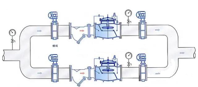
Installation of pressure reducing valves
1. The pressure-reducing valve sets installed vertically are generally set at a suitable height from the ground along the wall. The pressure-reducing valve sets installed horizontally are generally installed on the permanent operating platform.
2. Apply structural steels to the outside of two control valves (commonly used as globe valves) and load them into the wall to form a bracket, and the bypass pipe is also stuck on the bracket for leveling and alignment.
3. The pressure reducing valve shall be installed upright on the horizontal pipeline, and shall not tilt. The arrow on the valve body shall point to the direction of medium flow, and shall not be installed upside down.
4. Globe valves and high and low-pressure gauges shall be installed on both sides to observe the pressure changes before and after the valves. The diameter of the pipe behind the pressure-reducing valve should be 2 to 3 inches larger than the diameter of the inlet before the valve, and a bypass pipe should be installed ready for maintenance.
5. The pressure-equalizing pipe of membrane pressure reducing valves shall be connected to the low-pressure pipeline. Safety valves shall be set for low-pressure pipelines to ensure the safe operation of the system.
6. When used for steam decompression, a drain pipe should be set. For piping systems with high requirements for purification, a filter shall be set in front of the pressure-reducing valve.
7. After the installation of the pressure reducing valve set, the pressure reducing valve and safety valve shall be tested, flushed and adjusted according to the design requirements, and the adjusted marks shall be made.
8. When flushing the pressure reducing valve, close the inlet valve of the pressure reducer and open the flush valve for flushing.
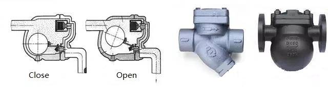
Installation of steam trap valves
The basic function of steam trap valves is to discharge condensed water, air and carbon dioxide gas from the steam system as soon as possible. At the same time, it can automatically prevent steam leakage to the maximum extent. There are many kinds of traps, each with a different performance.
According to different working principles of steam traps, they can be classified into the following three types:
Mechanical type:
Its works depend on the change of condensate level height in the steam trap, including floating ball type (the float is a closed hollow sphere), open-up float type (the float is a barrel type with an open-up mouth), open downward float type (the float is a barrel type with a mouth open-downward).
Thermostatic type:
Its acts depend on the change of liquid temperature, including bimetal type (the sensitive element is bi-metal), pressure type (the sensitive element is bellows or ink box, and volatile liquid is filled inside).
Thermodynamic type:
Its acts depend on the change of thermodynamic properties of the liquid.
Disc type:
Because of the different flow rates of liquid and gas under the same pressure, the different dynamic and static pressures are produced to drive the disc valve plate to act.
Pulse-type:
When condensed water with different temperatures passes through the two-pole series orifice plates, different pressures will be formed between the two-pole orifice plates, which will drive the valve disc to act.
Installation of steam traps
1. Globe valves should be set before and after, and filters should be set between the steam trap and the front globe valve to prevent dirt in condensed water from blocking the steam trap.
2. A check pipe should be set between the steam trap and the rear block valve to check whether the steam trap works normally. If a large amount of steam is emitted by opening the check pipe, it means that the steam trap is broken and needs maintenance.
3. The bypass pipe is set to discharge a large amount of condensed water at startup and reduce the displacement load of the steam trap.
4. When the steam trap is used to remove the condensate from the thermal equipment, it should be installed at the lower part of the thermal equipment, so that the condensate pipe can be connected to the steam trap vertically to prevent the thermal equipment from storing water.
5. The installation position should be as close to the drainage point as possible. If the distance is too far, air or steam will accumulate in the slender pipe in front of the steam trap.
6. When the horizontal pipeline of the steam main is too long, the drainage problem should be considered.
1. Carefully check whether the valve model and specification meet the drawing requirements.
2. Check whether the valve stem and disc are open flexibly and whether they are stuck or skewed.
3. Check whether the valve is damaged and whether the thread of the threaded valve is correct and intact.
4. Check whether the combination of the valve seat and the valve body is firm, and the connection between the valve disc and the valve seat, the valve cover and the valve body, and the valve stem and the valve disc.
5. Check whether the valve gasket, packing and fasteners (bolts) are suitable for the requirements of working medium properties.
6. Remove the old or long-standing pressure reducing valve, and clean the dust, sand and other sundries with water.
7. Remove the port cover; check the sealing degree, and the valve disc must be closed tightly.
Pressure test of the valve
Low-pressure, medium-pressure and high-pressure valves shall be subjected to strength test and leak test, and alloy steel valves shall be subjected to spectral analysis on their shells one by one, and the materials shall be rechecked.
1. Strength test of valves
The strength test of the valve is to check the leakage on the outer surface of the valve when the valve is open. For valves with PN≤32MPa, the test pressure is 1.5 times the nominal pressure, and the test time is not less than 5min until no leakage is found at the shell and packing gland.
2. Leakage test of valves
When the valve is completely closed, check whether the sealing surface of the valve is leaking. The test pressure of valves other than butterfly valves, check valves, foot valves and throttle valves shall generally be at nominal pressure. When the working pressure can be determined, the test can also be carried out at 1.25 times the working pressure. Under this condition, the valve can be qualified if no leakage happens to its disc sealing surface.
General provisions for valve installation
1. The installation position of the valve should not interfere with the operation, disassembly and maintenance of the equipment, pipeline and valve body itself, and at the same time, the intact and neat appearance of the assembly should be considered.
2. For valves on horizontal pipelines, the valve stem shall be installed upward or inclined at a certain angle, while the handwheel shall not be installed downward. The valve, valve stem and handwheel on the high-altitude pipeline can be installed horizontally, and the opening and closing of the valve can be operated remotely by the chain at the lower vertical position.
3. The arrangement should be symmetrical, neat and beautiful. On the premise that the process permits, the valve handwheel on the standpipe is most suitable for operation at chest height, generally 1.0—1.2m away from the ground. The valve stem must be installed in the direction of the operator.
4. The elevation of the centerline of valves on side-by-side risers should be consistent, and the clear distance between handwheels should not be less than 100mm. The valves on the side-by-side horizontal pipes should be staggered to reduce the pipe spacing.
5. When installing heavy valves on water pumps, heat exchangers and other equipment, valve supports shall be provided. When the valve is frequently operated and installed more than 1.8m away from the operation surface, a fixed operation platform shall be set.
6. If there is an arrow mark on the valve body, the direction of the arrow is the flow direction of the medium. When installing the valve, care should be taken that the arrow points in the same direction as the medium in the pipeline.
7. When installing the flanged valve, ensure that the end faces of the two flanges are parallel and concentric with each other, and do not use double gaskets.
8. When installing threaded valves, a threaded valve should be equipped with a union for easy disassembly. Ease of maintenance should be considered in the setting of a flexible joint. Usually, water flows through the valve first and then through the flexible joint.
Precautions for valve installation
1. The valve body material is made of cast iron, which is brittle, so it shall not be impacted by heavy objects.
2. When moving the valve, throwing is not allowed. When lifting and hoisting the valve, the rope should be tied to the valve body, and it is strictly forbidden to be tied to the handwheel, valve stem and flange bolt hole.
3. The valve should be installed in the most convenient place for operation, maintenance and overhaul, and it is forbidden to bury it underground. Check well chambers shall be set for valves on pipelines directly buried and in trenches, so as to facilitate the opening and closing and adjustment of valves.
4. Ensure that the threads are intact, and wrap flax, lead oil, or Teflon tape around the threads. When screwing, use a wrench to clamp the hexagonal valve body screwed into one end of the pipe.
5. When installing the flange valve, pay attention to tighten the connecting bolts along the diagonal direction, and apply even force when turning to prevent the gasket from wandering or causing deformation and damage to the valve body.
6. The valve shall be kept closed during installation. For threaded valves close to the wall, it is often necessary to remove the stem disc and handwheel before turning. During disassembly, the manual wheel should be screwed to keep the valve open before disassembly.
Installation of common valves
Installation of gate valves, globe valves and check valves:
Gate valves are valves that use wedge discs to control the opening and closing, and adjusts the pipeline flow and open and close the pipeline by changing the cross-section. Gate valves are mostly used for pipelines that fully open or close fluid media. Gate valves are generally installed without directional requirements, but they cannot be inverted.
Globe valves are valves that use discs to control opening and closing. By changing the gap between the valve disc and the valve seat, that is, by changing the size of the channel section, the medium flow rate can be adjusted or the medium passage can be cut off. Pay attention to the flow direction of the fluid when installing the globe valve. The principle that must be observed when installing the globe valve is that the fluid in the pipeline passes through the valve hole from bottom to top, which is commonly known as "low in and high out", and it is not allowed to install it upside down.
Check valves, also known as non-return valves and one-way valves, are valves that open and close automatically under the action of pressure difference before and after the valve. Their function is to make the medium only flow in one direction while preventing the medium from flowing backward. Check valves are of lifting types, swing types and butterfly types according to their different structures. Lifting check valves can be divided into horizontal and vertical types. When installing the check valve, pay attention to the flowing direction of the medium, and do not install it upside down.
Installation of pressure reducing valves
Pressure-reducing valves are valves that reduce the inlet pressure to a certain required outlet pressure through adjustment, thus keeps the outlet pressure stable automatically by relying on the energy of the medium itself.
From the point of view of hydrodynamics, the pressure reducing valve is a throttling element with variable local resistance, that is, by changing the throttling area, the flow rate and kinetic energy of the fluid are changed, resulting in different pressure losses, thus achieving the purpose of pressure reduction. Then, relying on the adjustment of the control and adjustment system, the fluctuation of the pressure behind the valve is balanced with the spring force, so that the pressure behind the valve remains constant within a certain error range.
Installation of pressure reducing valves
1. The pressure-reducing valve sets installed vertically are generally set at a suitable height from the ground along the wall. The pressure-reducing valve sets installed horizontally are generally installed on the permanent operating platform.
2. Apply structural steels to the outside of two control valves (commonly used as globe valves) and load them into the wall to form a bracket, and the bypass pipe is also stuck on the bracket for leveling and alignment.
3. The pressure reducing valve shall be installed upright on the horizontal pipeline, and shall not tilt. The arrow on the valve body shall point to the direction of medium flow, and shall not be installed upside down.
4. Globe valves and high and low-pressure gauges shall be installed on both sides to observe the pressure changes before and after the valves. The diameter of the pipe behind the pressure-reducing valve should be 2 to 3 inches larger than the diameter of the inlet before the valve, and a bypass pipe should be installed ready for maintenance.
5. The pressure-equalizing pipe of membrane pressure reducing valves shall be connected to the low-pressure pipeline. Safety valves shall be set for low-pressure pipelines to ensure the safe operation of the system.
6. When used for steam decompression, a drain pipe should be set. For piping systems with high requirements for purification, a filter shall be set in front of the pressure-reducing valve.
7. After the installation of the pressure reducing valve set, the pressure reducing valve and safety valve shall be tested, flushed and adjusted according to the design requirements, and the adjusted marks shall be made.
8. When flushing the pressure reducing valve, close the inlet valve of the pressure reducer and open the flush valve for flushing.
Installation of steam trap valves
The basic function of steam trap valves is to discharge condensed water, air and carbon dioxide gas from the steam system as soon as possible. At the same time, it can automatically prevent steam leakage to the maximum extent. There are many kinds of traps, each with a different performance.
According to different working principles of steam traps, they can be classified into the following three types:
Mechanical type:
Its works depend on the change of condensate level height in the steam trap, including floating ball type (the float is a closed hollow sphere), open-up float type (the float is a barrel type with an open-up mouth), open downward float type (the float is a barrel type with a mouth open-downward).
Thermostatic type:
Its acts depend on the change of liquid temperature, including bimetal type (the sensitive element is bi-metal), pressure type (the sensitive element is bellows or ink box, and volatile liquid is filled inside).
Thermodynamic type:
Its acts depend on the change of thermodynamic properties of the liquid.
Disc type:
Because of the different flow rates of liquid and gas under the same pressure, the different dynamic and static pressures are produced to drive the disc valve plate to act.
Pulse-type:
When condensed water with different temperatures passes through the two-pole series orifice plates, different pressures will be formed between the two-pole orifice plates, which will drive the valve disc to act.
Installation of steam traps
1. Globe valves should be set before and after, and filters should be set between the steam trap and the front globe valve to prevent dirt in condensed water from blocking the steam trap.
2. A check pipe should be set between the steam trap and the rear block valve to check whether the steam trap works normally. If a large amount of steam is emitted by opening the check pipe, it means that the steam trap is broken and needs maintenance.
3. The bypass pipe is set to discharge a large amount of condensed water at startup and reduce the displacement load of the steam trap.
4. When the steam trap is used to remove the condensate from the thermal equipment, it should be installed at the lower part of the thermal equipment, so that the condensate pipe can be connected to the steam trap vertically to prevent the thermal equipment from storing water.
5. The installation position should be as close to the drainage point as possible. If the distance is too far, air or steam will accumulate in the slender pipe in front of the steam trap.
6. When the horizontal pipeline of the steam main is too long, the drainage problem should be considered.
