Posted Mar 30, 2021
Valve Buffer Structure for Reducing Vibration and Noise of Valve Opening and Closing
The valve relies on the cooperation of the valve body and the disk to control the conveying medium. After the valve is closed, the pressure at the inlet end and the outlet end are different, resulting in dropout voltage. When the valve is opened, the existence of the differential pressure will cause a huge instantaneous impact force on the valve components and pipelines when the medium passes through the valve, resulting in vibration of the valve accompanied by noise. Vibration has an impact on the sealing performance, service life and other testing equipment of the valve and its connected pipeline. Under some special high-pressure conditions, especially the valves used in high-pressure pipeline system, the vibration is particularly severe, which can not meet the requirements of stable operation, small vibration amplitude and low noise.
The valve buffer structure is characterized in that a valve disk matched with the valve body is provided with a central through hole and two symmetrically arranged bypass holes (not limiting to two), and the bypass holes are communicated with the central through hole. A sealing seat is arranged at the central through hole from the sealing end face of the valve disk to the bypass hole, and a sealing disk is arranged on the sealing seat to form sealing assembly. When the sealing assembly is closed, the bypass hole is not communicated with the lower central through hole; when the sealing assembly is open, the bypass hole communicates with the lower central through hole, connecting the inlet and outlet ends of the valve. The sealing disk is connected with one end of the transmission rod, and the other end of the transmission rod extends out of the central through hole and is connected with the driving mechanism. The height of the limiting groove is the moving distance of the sealing disk in the central through hole of the valve disk, which should meet the requirement that the central through hole at the lower part of the valve disk is communicated with the bypass hole after the sealing assembly is opened.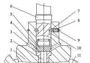 1.Valve Disk 2.Central Through Hole 3.Bypass Hole 4.Seal Receptacle 5.Sealing Disk
6.Transmission Rod 7.Limiting Ball 8.Limiting Screw 9.Through Hole 10.Limiting Groove
11.Valve Body
When the valve is opened, the transmission rod rises led by the driving mechanism, and the sealing disk connected with it thereupon rises. At this time, the valve disk does not move, and the sealing assembly is opened first. The medium will enter from the inlet end to the outlet end of the valve through the central through hole and bypass hole, and the pressure at the inlet and outlet ends of the valve will be balanced by a small amount of flowing medium. As the transmission rod continues to rise, under the restriction of the limiting mechanism, the sealing disk and the valve disk move up at the same time, and the valve opens. On the contrary, when the transmission rod moves down, the sealing assembly is closed first, and as the transmission rod continues to move down, the valve closes.
The valve buffer structure can reduce vibration and noise by adjusting the pressure at the inlet and outlet of the valve, and ensure the service performance of the valve. The valve disk is provided with a central through hole and a bypass hole communicated with it, between which sealing assembly is arranged. The sealing disk of the sealing assembly is connected with a transmission rod, and a limiting mechanism is arranged between them. A through hole is formed on the valve disk wall and a limiting groove is formed on the transmission rod at the position opposite to the through hole. The limiting ball is located in the through hole and the limiting groove, and a limiting screw for limiting the movement of the limiting ball is arranged in the through hole.
The valve buffering structure is that a central through hole and at least two symmetrically arranged bypass holes are arranged on the valve disk of the valve. The central through hole is communicated with the bypass hole, which can communicate the inlet and outlet of the valve. The sealing assembly is arranged between the central through hole and the bypass hole for connecting or disconnecting them. The sealing disk of the sealing assembly is connected with the transmission rod, and a limiting mechanism is arranged between them, which limits the moving range of the transmission rod along the central through hole of the valve disk. When the transmission rod moves, it first drives the sealing disk to move then the valve disk. In the process of opening the valve, some medium enters the outlet end from the inlet end of the valve through the central through hole and the bypass hole, so as to balance the pressure at the inlet and outlet of the valve, reducing the pressure difference and the impact of medium on the valve components.
A buffer structure is arranged on the valve disk, which reduces the pressure difference between the inlet and outlet ends of the valve, realizing pressure balance and alleviating the impact of medium on the valve. The valve buffer structure is suitable for high-pressure pipeline system, with stable opening and closing operation, small vibration amplitude and low noise, which can prolong the service life of components and meet the requirements of working conditions.
The valve buffer structure is characterized in that a valve disk matched with the valve body is provided with a central through hole and two symmetrically arranged bypass holes (not limiting to two), and the bypass holes are communicated with the central through hole. A sealing seat is arranged at the central through hole from the sealing end face of the valve disk to the bypass hole, and a sealing disk is arranged on the sealing seat to form sealing assembly. When the sealing assembly is closed, the bypass hole is not communicated with the lower central through hole; when the sealing assembly is open, the bypass hole communicates with the lower central through hole, connecting the inlet and outlet ends of the valve. The sealing disk is connected with one end of the transmission rod, and the other end of the transmission rod extends out of the central through hole and is connected with the driving mechanism. The height of the limiting groove is the moving distance of the sealing disk in the central through hole of the valve disk, which should meet the requirement that the central through hole at the lower part of the valve disk is communicated with the bypass hole after the sealing assembly is opened.
1.Valve Disk 2.Central Through Hole 3.Bypass Hole 4.Seal Receptacle 5.Sealing Disk 6.Transmission Rod 7.Limiting Ball 8.Limiting Screw 9.Through Hole 10.Limiting Groove
11.Valve Body
When the valve is opened, the transmission rod rises led by the driving mechanism, and the sealing disk connected with it thereupon rises. At this time, the valve disk does not move, and the sealing assembly is opened first. The medium will enter from the inlet end to the outlet end of the valve through the central through hole and bypass hole, and the pressure at the inlet and outlet ends of the valve will be balanced by a small amount of flowing medium. As the transmission rod continues to rise, under the restriction of the limiting mechanism, the sealing disk and the valve disk move up at the same time, and the valve opens. On the contrary, when the transmission rod moves down, the sealing assembly is closed first, and as the transmission rod continues to move down, the valve closes.
The valve buffer structure can reduce vibration and noise by adjusting the pressure at the inlet and outlet of the valve, and ensure the service performance of the valve. The valve disk is provided with a central through hole and a bypass hole communicated with it, between which sealing assembly is arranged. The sealing disk of the sealing assembly is connected with a transmission rod, and a limiting mechanism is arranged between them. A through hole is formed on the valve disk wall and a limiting groove is formed on the transmission rod at the position opposite to the through hole. The limiting ball is located in the through hole and the limiting groove, and a limiting screw for limiting the movement of the limiting ball is arranged in the through hole.
The valve buffering structure is that a central through hole and at least two symmetrically arranged bypass holes are arranged on the valve disk of the valve. The central through hole is communicated with the bypass hole, which can communicate the inlet and outlet of the valve. The sealing assembly is arranged between the central through hole and the bypass hole for connecting or disconnecting them. The sealing disk of the sealing assembly is connected with the transmission rod, and a limiting mechanism is arranged between them, which limits the moving range of the transmission rod along the central through hole of the valve disk. When the transmission rod moves, it first drives the sealing disk to move then the valve disk. In the process of opening the valve, some medium enters the outlet end from the inlet end of the valve through the central through hole and the bypass hole, so as to balance the pressure at the inlet and outlet of the valve, reducing the pressure difference and the impact of medium on the valve components.
A buffer structure is arranged on the valve disk, which reduces the pressure difference between the inlet and outlet ends of the valve, realizing pressure balance and alleviating the impact of medium on the valve. The valve buffer structure is suitable for high-pressure pipeline system, with stable opening and closing operation, small vibration amplitude and low noise, which can prolong the service life of components and meet the requirements of working conditions.
News
Industry News
Back to List
