Posted Nov 23, 2022
Cracking Reasons for Deformed 316L Stainless Steel Seamless Pipes
With the rapid development of the electric power industry, cable threading pipe has been widely popularized and applied in the process of national grid construction and transformation. In daily life, people usually choose rigid PVC pipe with good corrosion resistance and insulation performance as the cable threading pipe material. In the industrial field, according to different service environments, materials such as carbon steel and stainless steel are often used. Among them, 316L stainless steel is widely used in extremely harsh industrial environments because of its excellent corrosion resistance and processability.
The cold deformed 316L stainless steel cable threading seamless pipe used in an oil field cracked, the outer surface of the pipe contacted with crude oil containing H2S and C1-, and the inside was filled with dry sand and copper core. In order to find out the causes of pipeline cracking, the physical and chemical inspection of the failed pipeline was carried out by means of microstructure observation, mechanical property test and fracture analysis, so as to prevent the recurrence of similar problems.
Physical and chemical inspection
Macroscopic morphology analysis
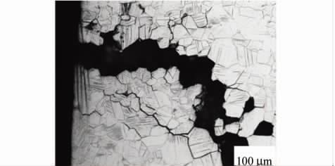
The specification of 316L stainless steel cable threading seamless pipe is 25mm×2.1mm, and the delivery state is solid solution+pickling passivation. During the cable assembly process, it will undergo one drawing deformation treatment. After measurement, the actual size of the pipeline is 21.4x2.1 mm. After a period of service, the surface of the pipeline will crack, as shown in Figure 1. The macroscopic and microscopic morphology of the crack was observed by stereomicroscope, as shown in Figure 2. The propagation direction of the main crack is transverse to the pipeline, and both ends of the crack form dendritic branches, forming secondary cracks. There are a lot of shallow pits on the surface of the pipeline, and the surface quality is poor, as shown in Figure 2(a). It is observed under the high-power metallographic microscope that there are a large number of local corrosion morphology along the grain boundary in the area around the crack, as shown in Figure 2(b). It is speculated that the corrosion area of shallow pits on the surface of the pipeline is the location where the intergranular corrosion degree is serious.
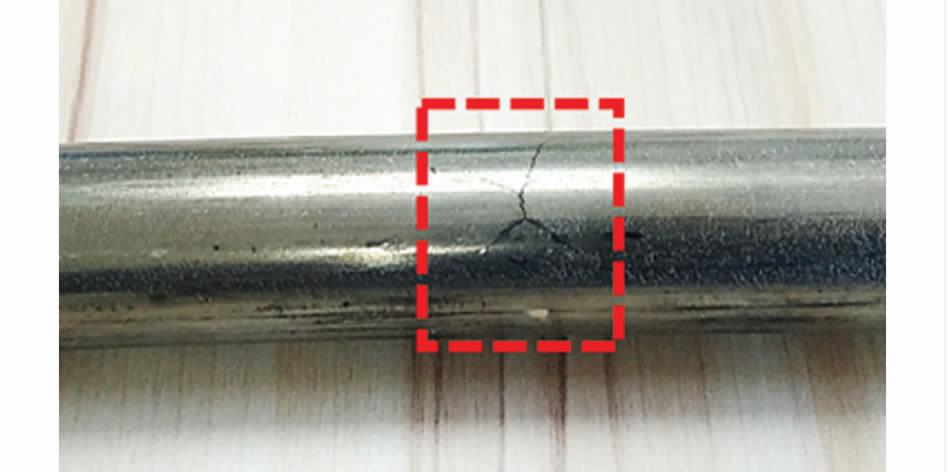
Fig.1 Macro morphology of cracks location on the surface of the failed pipeline
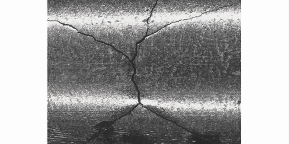
(a) Macroscopic morphology
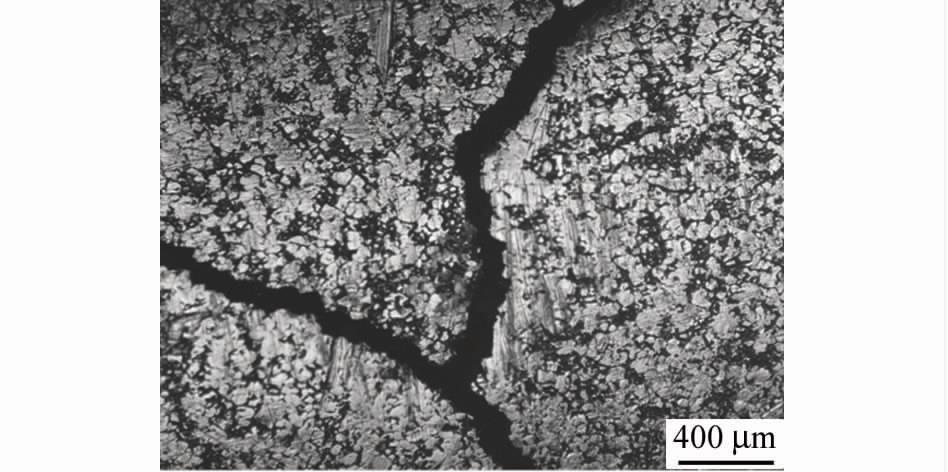
(b) Microstructure
Fig.2 Macro and micromorphology (a,b) of cracks
Chemical composition analysis
According to the standard GB/T 11170-2008 "Determination of Multi-element Content in Stainless Steel", the chemical composition spectrum of the failed pipeline was analyzed by spark discharge atomic emission spectrometry. According to GB/T 20123-2006 "Determination of total carbon and sulfur content in steel", infrared absorption method after combustion in high-frequency induction furnace, GB/T 11261-2006 "Determination of oxygen content in steel by pulse heating inert gas melting-infrared absorption method", GB/T 20124-2006 "Determination of nitrogen content in steel by inert gas melting thermal conductivity method", GB/T 223. Refer to ASTM A213/A213M-18 "Specification for Seamless Ferrite and Austenite Alloy Steel Pipes for Boilers, Superheaters and Heat Exchangers" for the chemical composition of 316L stainless steel, and the chemical composition of the failed pipe meets the standard requirements. According to the standard GB/T 11170-2008 "Determination of Multi-element Content in Stainless Steel", the chemical composition spectrum of the failed pipeline was analyzed by spark discharge atomic emission spectrometry. According to GB/T 20123-2006 "Determination of total carbon and sulfur content in steel", infrared absorption method after combustion in high-frequency induction furnace, GB/T 11261-2006 "Determination of oxygen content in steel by pulse heating inert gas melting-infrared absorption method", GB/T 20124-2006 "Determination of nitrogen content in steel by inert gas melting thermal conductivity method", GB/T 223. Refer to ASTM A213/A213M-18 "Specification for Seamless Ferrite and Austenite Alloy Steel Pipes for Boilers, Superheaters and Heat Exchangers" for the chemical composition of 316L stainless steel, and the chemical composition of the failed pipe meets the standard requirements.
Table.1 Chemical composition of the failed pipeline (mass fraction)
Microstructure analysis
Samples were taken from the crack of the failed pipeline, etched with hydrochloric acid and alcohol, and then the microstructure was observed. It can be seen from Figure 3 that the microstructure of the failed pipeline is a typical cold deformation structure, and there are a lot of slip bands in the grain. According to GB/T 6394-2017 "Determination Method of Average Grain Size of Metals", GB/T 13298-2015 "Inspection Method of Metal Microstructure" and GB/T 10561-2005 "Microscopic Inspection Method of Standard Rating Chart for Determination of Non-metallic Inclusions in Steel", the grain size, precipitated phase and inclusions of the failed pipeline were rated respectively. The results showed that the failed pipeline
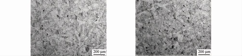
(a) Transverse microstructure
(b) Longitudinal microstructure
(c) Precipitated phase
(d) Inclusion
Fig.3 Microstructure of failed pipeline: (a) lateral macrostructure; (b)longitudinal microstructure; (c)precipitation phase; (d)inclusion
Mechanical property analysis
The failed pipeline is processed by cold drawing process, and the failed pipeline is treated by solution annealing at 1080℃ for 10Min. According to ASTM A370-17a "Standard Test Methods and Definitions for Mechanical Properties Test of Steel Products", samples were taken from the original and solution annealed failure pipes, and tensile properties at room temperature and Brinell hardness tests were conducted. It can be seen from Table 2 that compared with the solution-annealed pipeline, the original pipeline has higher strength and hardness, with its yield strength of 689MPa, a tensile strength of 848MPa and an average Brinell hardness of 218HB. A large number of studies show that the high strength and hardness of materials will greatly increase the possibility of stress corrosion cracking of materials in a corrosive environment.
Table.2 Mechanical properties of failed pipeline
Residual stress analysis
According to RCC-M MC 1360-2007 Test and Evaluation of Residual Tensile Stress of Austenitic Stainless Steel for Heat Exchangers, the residual stress is tested by sampling from the failed pipeline, as shown in Figure 4, and the test results are shown in Table 3. After opening the failed pipeline, the opening width of the notch is about 0.92 mm. According to the calculation, there is a high residual stress in the failed pipeline, about 222 MPa.
(a) Test pattern
(b) Incision morphology
Fig.4 Residual stress test sample and its notch morphology of failed pipeline
Tab.3 Residual stress test results of failed pipeline
Fracture morphology
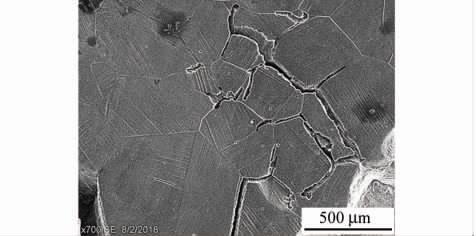
Sample the crack section on the surface of the failed pipeline, grind and polish the crack section, and then etch the crack section with hydrochloric acid alcohol. As can be seen from Figure 5, there are a large number of cold deformation slip zones inside the grain, and the cracks originate from the outer surface of the pipeline and gradually expand to the inner surface, and the main cracks run through the entire wall thickness of the pipeline; There are a large number of tiny secondary cracks at the crack initiation place on the outer surface of the pipeline. Both the primary crack and the secondary crack propagate along the grain boundary, and some areas still have the phenomenon of grain shedding, which is a typical intergranular stress corrosion cracking.
(a) Sectional structure
(b) External surface tissue
Fig.5 Cross-section and outer surface microstructure (a,b) of surface cracks of failed pipeline
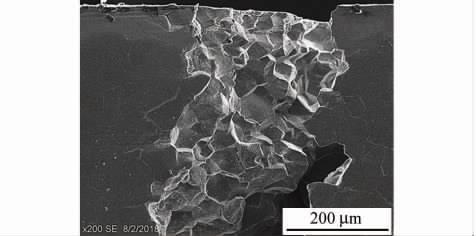
A scanning electron microscope (SEM) was used to observe the crack cross-section, as shown in Figure 6. It can be seen from fig. 6 that there are a large number of cold deformation slip bands inside the grain, and there is basically no precipitated phase at the grain boundary and inside the grain. At the crack tip, all microcracks propagate and crack along the grain boundary; The fracture at the crack initiation is characterized by crystal sugar-like intergranular cleavage fracture, which is a typical brittle fracture.
(a) Crack tip
(b) Crack initiation site
Fig.6 Fracture morphology of failed pipeline: (a)crack tip; (b)crack initiation area
Failure reason analysis
It is found that deformation-induced martensite is the key factor of stress corrosion cracking (SCC) in cold-deformed 304L stainless steel. Zuo Yu and others think that deformed martensite is not only beneficial to the nucleation of stress corrosion cracks but also easy to selectively dissolve in stainless steel in a corrosive environment, which leads to crack propagation. For austenitic corrosion-resistant alloy steel with high alloy content, deformation-induced martensite is usually difficult to occur at room temperature. Gu Xuedong and others found that the austenitic structure of 316l stainless steel has high stability, and only a small amount of deformed martensite is produced by 30% cold deformation. In austenitic stainless steel with high alloy content, it is difficult to induce martensite by cold deformation, but defects such as high-density dislocation can be introduced into the metal matrix. According to the slip dissolution mechanism model of stress corrosion of metal materials, under the action of stress, the internal dislocation of metal materials will move along the slip, forming a slip step on the metal surface, leading to the rupture of passivation film and the stress corrosion channel in the corrosive environment, which eventually leads to the stress corrosion cracking failure of metal.
It can be seen from the above test results that the chemical composition of the failed pipeline meets the standard requirements, and there are no precipitated phases and inclusions at the grain boundary and inside the grain. The actual service environment of the pipeline is crude oil containing H2S and Cl-, and the outer wall of the pipeline is in direct contact with a corrosive medium, resulting in intergranular corrosion on the surface. The crack started to sprout from the outer surface of the pipeline, then gradually expanded along the grain to the inner surface of the pipeline, and the fracture finally showed the characteristics of crystal sugar-like brittle cleavage fracture. Stress cracking is a kind of damage form of metal materials under the combined action of corrosive medium and tensile and compressive stress. According to different metal materials and their service environments, H2S stress corrosion cracking of metal materials is mainly divided into the hydrogen-induced cracking type and anodic dissolution type. When the stress corrosion cracking process is controlled by hydrogen generated by hydrogen evolution reaction, it is generally called hydrogen-induced cracking type stress corrosion cracking. The hydrogen embrittlement of metal in a wet H2S environment is closely related to the strength and hardness of the material. The American Society of Corrosion Engineers (NACE) and API gravity (API) standard NACE MR 0175/ISO 15156-2009 "Petroleum and Natural Gas Industry-Materials for H2S-containing Environment in Oil and Gas Exploitation" controls the hardness of materials below 22 HRC. According to SH/T3075-2009 Specification for Material Selection of Steel Pressure Vessels in Petrochemical Industry, in a wet H2S environment with H2S partial pressure greater than or equal to 0.000 35 MPa and total pressure greater than 0.46 MPa, the hardness of weld and heat affected zone of materials shall not be greater than 200 HB. When the hardness exceeds the standard, the possibility of hydrogen embrittlement of materials will be greatly increased. Through the test results of strength, hardness and residual stress, it is found that the strength and hardness of the original failed pipeline are higher than those of the solution-annealed pipeline, and there is a higher residual stress. The higher strength, hardness and residual stress will greatly improve the hydrogen embrittlement sensitivity of the material in a wet H2S environment. There are toxic agents such as S2- and HS- in the wet environment, and a large amount of hydrogen diffuses into the metal materials and interacts with various defects in the metal, which induces hydrogen embrittlement cracking of the metal materials. In addition, the content of solid solution hydrogen in the failed pipeline is 6 μ g/g, which often affects the mechanical properties of metal materials. Through the study of annealed pure iron (σ b = 82 MPa), it is found that 5 ~ 7 μ g/g of solid solution hydrogen will lead to the loss of hydrogen-induced plasticity of the material above 65%. The strength of the original failed pipeline is high, so it is speculated that the solution hydrogen may promote the hydrogen embrittlement of the failed pipeline. Through the microstructure of the crack section of the failed pipeline, it can be found that there are a large number of cold deformation slip bands in the grain. Qiao Lijie's research shows that reversible hydrogen traps such as dislocations and slip bands play a greater role in hydrogen embrittlement than irreversible hydrogen traps such as inclusions and precipitates in metal materials. To sum up, after cold drawing deformation, the high-density dislocation and slip band of 316l stainless steel are introduced, which greatly improves the strength and hardness of the material, and there is high residual stress in the material, which is the main reason for the hydrogen-induced stress corrosion cracking of the material in a wet H2S environment.
Conclusion
(1) intergranular stress corrosion cracking occurred in cold deformed 316l stainless steel cable threading seamless pipe in a service environment.
(2) The chemical composition of the failed pipeline meets the standard requirements, and there are no precipitates and inclusions at the grain boundary and inside the grain. However, the high-density dislocation and cold deformation slip belt introduced after drawing deformation greatly improve its strength and hardness, and there is high residual stress inside the material, which is the main reason for the increase of pipeline brittleness and hydrogen-induced stress corrosion cracking in a wet H2S environment.
(3) It is suggested that the cable manufacturer optimize the manufacturing process, and add a solution annealing process to the 316l stainless steel cable conduit after drawing deformation, so as to eliminate the high-density dislocation and cold deformation slip zone introduced into the material after drawing the deformation, thus reducing its stress corrosion cracking sensitivity in a wet H2S environment.
The cold deformed 316L stainless steel cable threading seamless pipe used in an oil field cracked, the outer surface of the pipe contacted with crude oil containing H2S and C1-, and the inside was filled with dry sand and copper core. In order to find out the causes of pipeline cracking, the physical and chemical inspection of the failed pipeline was carried out by means of microstructure observation, mechanical property test and fracture analysis, so as to prevent the recurrence of similar problems.
Physical and chemical inspection
Macroscopic morphology analysis
The specification of 316L stainless steel cable threading seamless pipe is 25mm×2.1mm, and the delivery state is solid solution+pickling passivation. During the cable assembly process, it will undergo one drawing deformation treatment. After measurement, the actual size of the pipeline is 21.4x2.1 mm. After a period of service, the surface of the pipeline will crack, as shown in Figure 1. The macroscopic and microscopic morphology of the crack was observed by stereomicroscope, as shown in Figure 2. The propagation direction of the main crack is transverse to the pipeline, and both ends of the crack form dendritic branches, forming secondary cracks. There are a lot of shallow pits on the surface of the pipeline, and the surface quality is poor, as shown in Figure 2(a). It is observed under the high-power metallographic microscope that there are a large number of local corrosion morphology along the grain boundary in the area around the crack, as shown in Figure 2(b). It is speculated that the corrosion area of shallow pits on the surface of the pipeline is the location where the intergranular corrosion degree is serious.
Fig.1 Macro morphology of cracks location on the surface of the failed pipeline
(a) Macroscopic morphology
(b) Microstructure
Fig.2 Macro and micromorphology (a,b) of cracks
Chemical composition analysis
According to the standard GB/T 11170-2008 "Determination of Multi-element Content in Stainless Steel", the chemical composition spectrum of the failed pipeline was analyzed by spark discharge atomic emission spectrometry. According to GB/T 20123-2006 "Determination of total carbon and sulfur content in steel", infrared absorption method after combustion in high-frequency induction furnace, GB/T 11261-2006 "Determination of oxygen content in steel by pulse heating inert gas melting-infrared absorption method", GB/T 20124-2006 "Determination of nitrogen content in steel by inert gas melting thermal conductivity method", GB/T 223. Refer to ASTM A213/A213M-18 "Specification for Seamless Ferrite and Austenite Alloy Steel Pipes for Boilers, Superheaters and Heat Exchangers" for the chemical composition of 316L stainless steel, and the chemical composition of the failed pipe meets the standard requirements. According to the standard GB/T 11170-2008 "Determination of Multi-element Content in Stainless Steel", the chemical composition spectrum of the failed pipeline was analyzed by spark discharge atomic emission spectrometry. According to GB/T 20123-2006 "Determination of total carbon and sulfur content in steel", infrared absorption method after combustion in high-frequency induction furnace, GB/T 11261-2006 "Determination of oxygen content in steel by pulse heating inert gas melting-infrared absorption method", GB/T 20124-2006 "Determination of nitrogen content in steel by inert gas melting thermal conductivity method", GB/T 223. Refer to ASTM A213/A213M-18 "Specification for Seamless Ferrite and Austenite Alloy Steel Pipes for Boilers, Superheaters and Heat Exchangers" for the chemical composition of 316L stainless steel, and the chemical composition of the failed pipe meets the standard requirements.
Table.1 Chemical composition of the failed pipeline (mass fraction)
| element | C | Si | Mn | P | S | Cr | Mo | Ni | N | H | O |
| rated value | ≤0.035 | ≤1.0 | ≤2.0 | ≤0.045 | ≤0.030 | 6.0-18.0 | 2.00-3.00 | 0.0-14.0 | - | - | - |
| measured value | 0.015 | 0.31 | 0.64 | 0.034 | 0.0058 | 16.7 | 2.01 | 10.2 | 0.065 | 0.0006 | 0.0025 |
Microstructure analysis
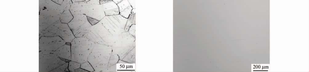
Samples were taken from the crack of the failed pipeline, etched with hydrochloric acid and alcohol, and then the microstructure was observed. It can be seen from Figure 3 that the microstructure of the failed pipeline is a typical cold deformation structure, and there are a lot of slip bands in the grain. According to GB/T 6394-2017 "Determination Method of Average Grain Size of Metals", GB/T 13298-2015 "Inspection Method of Metal Microstructure" and GB/T 10561-2005 "Microscopic Inspection Method of Standard Rating Chart for Determination of Non-metallic Inclusions in Steel", the grain size, precipitated phase and inclusions of the failed pipeline were rated respectively. The results showed that the failed pipeline
(a) Transverse microstructure
(b) Longitudinal microstructure
(c) Precipitated phase
(d) Inclusion
Fig.3 Microstructure of failed pipeline: (a) lateral macrostructure; (b)longitudinal microstructure; (c)precipitation phase; (d)inclusion
Mechanical property analysis
The failed pipeline is processed by cold drawing process, and the failed pipeline is treated by solution annealing at 1080℃ for 10Min. According to ASTM A370-17a "Standard Test Methods and Definitions for Mechanical Properties Test of Steel Products", samples were taken from the original and solution annealed failure pipes, and tensile properties at room temperature and Brinell hardness tests were conducted. It can be seen from Table 2 that compared with the solution-annealed pipeline, the original pipeline has higher strength and hardness, with its yield strength of 689MPa, a tensile strength of 848MPa and an average Brinell hardness of 218HB. A large number of studies show that the high strength and hardness of materials will greatly increase the possibility of stress corrosion cracking of materials in a corrosive environment.
Table.2 Mechanical properties of failed pipeline
| Failure pipeline | yield strength/MPa | tensile strength/MPa | Hardness/HB |
| Primitive state | 689 | 848 | 218 |
| Solution annealed state | 302 | 575 | 154 |
Residual stress analysis
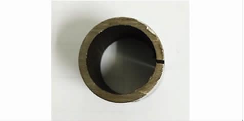
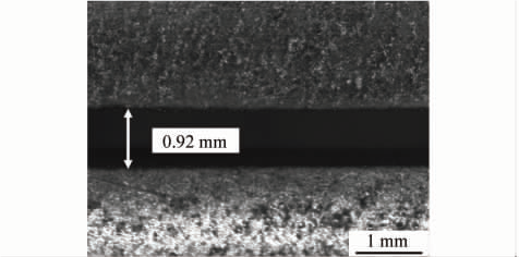
According to RCC-M MC 1360-2007 Test and Evaluation of Residual Tensile Stress of Austenitic Stainless Steel for Heat Exchangers, the residual stress is tested by sampling from the failed pipeline, as shown in Figure 4, and the test results are shown in Table 3. After opening the failed pipeline, the opening width of the notch is about 0.92 mm. According to the calculation, there is a high residual stress in the failed pipeline, about 222 MPa.
(a) Test pattern
(b) Incision morphology
Fig.4 Residual stress test sample and its notch morphology of failed pipeline
Tab.3 Residual stress test results of failed pipeline
| Initial diameter of pipeline/mm | Diameter of cut pipe/mm | Pipe wall thickness/mm | residual stress/MPa |
| 21.414 | 21.64 | 2.060 | 222.64 |
Fracture morphology
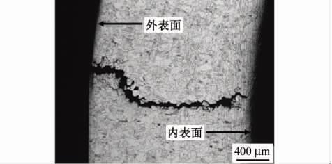
Sample the crack section on the surface of the failed pipeline, grind and polish the crack section, and then etch the crack section with hydrochloric acid alcohol. As can be seen from Figure 5, there are a large number of cold deformation slip zones inside the grain, and the cracks originate from the outer surface of the pipeline and gradually expand to the inner surface, and the main cracks run through the entire wall thickness of the pipeline; There are a large number of tiny secondary cracks at the crack initiation place on the outer surface of the pipeline. Both the primary crack and the secondary crack propagate along the grain boundary, and some areas still have the phenomenon of grain shedding, which is a typical intergranular stress corrosion cracking.
(a) Sectional structure
(b) External surface tissue
Fig.5 Cross-section and outer surface microstructure (a,b) of surface cracks of failed pipeline
A scanning electron microscope (SEM) was used to observe the crack cross-section, as shown in Figure 6. It can be seen from fig. 6 that there are a large number of cold deformation slip bands inside the grain, and there is basically no precipitated phase at the grain boundary and inside the grain. At the crack tip, all microcracks propagate and crack along the grain boundary; The fracture at the crack initiation is characterized by crystal sugar-like intergranular cleavage fracture, which is a typical brittle fracture.
(a) Crack tip
(b) Crack initiation site
Fig.6 Fracture morphology of failed pipeline: (a)crack tip; (b)crack initiation area
Failure reason analysis
It is found that deformation-induced martensite is the key factor of stress corrosion cracking (SCC) in cold-deformed 304L stainless steel. Zuo Yu and others think that deformed martensite is not only beneficial to the nucleation of stress corrosion cracks but also easy to selectively dissolve in stainless steel in a corrosive environment, which leads to crack propagation. For austenitic corrosion-resistant alloy steel with high alloy content, deformation-induced martensite is usually difficult to occur at room temperature. Gu Xuedong and others found that the austenitic structure of 316l stainless steel has high stability, and only a small amount of deformed martensite is produced by 30% cold deformation. In austenitic stainless steel with high alloy content, it is difficult to induce martensite by cold deformation, but defects such as high-density dislocation can be introduced into the metal matrix. According to the slip dissolution mechanism model of stress corrosion of metal materials, under the action of stress, the internal dislocation of metal materials will move along the slip, forming a slip step on the metal surface, leading to the rupture of passivation film and the stress corrosion channel in the corrosive environment, which eventually leads to the stress corrosion cracking failure of metal.
It can be seen from the above test results that the chemical composition of the failed pipeline meets the standard requirements, and there are no precipitated phases and inclusions at the grain boundary and inside the grain. The actual service environment of the pipeline is crude oil containing H2S and Cl-, and the outer wall of the pipeline is in direct contact with a corrosive medium, resulting in intergranular corrosion on the surface. The crack started to sprout from the outer surface of the pipeline, then gradually expanded along the grain to the inner surface of the pipeline, and the fracture finally showed the characteristics of crystal sugar-like brittle cleavage fracture. Stress cracking is a kind of damage form of metal materials under the combined action of corrosive medium and tensile and compressive stress. According to different metal materials and their service environments, H2S stress corrosion cracking of metal materials is mainly divided into the hydrogen-induced cracking type and anodic dissolution type. When the stress corrosion cracking process is controlled by hydrogen generated by hydrogen evolution reaction, it is generally called hydrogen-induced cracking type stress corrosion cracking. The hydrogen embrittlement of metal in a wet H2S environment is closely related to the strength and hardness of the material. The American Society of Corrosion Engineers (NACE) and API gravity (API) standard NACE MR 0175/ISO 15156-2009 "Petroleum and Natural Gas Industry-Materials for H2S-containing Environment in Oil and Gas Exploitation" controls the hardness of materials below 22 HRC. According to SH/T3075-2009 Specification for Material Selection of Steel Pressure Vessels in Petrochemical Industry, in a wet H2S environment with H2S partial pressure greater than or equal to 0.000 35 MPa and total pressure greater than 0.46 MPa, the hardness of weld and heat affected zone of materials shall not be greater than 200 HB. When the hardness exceeds the standard, the possibility of hydrogen embrittlement of materials will be greatly increased. Through the test results of strength, hardness and residual stress, it is found that the strength and hardness of the original failed pipeline are higher than those of the solution-annealed pipeline, and there is a higher residual stress. The higher strength, hardness and residual stress will greatly improve the hydrogen embrittlement sensitivity of the material in a wet H2S environment. There are toxic agents such as S2- and HS- in the wet environment, and a large amount of hydrogen diffuses into the metal materials and interacts with various defects in the metal, which induces hydrogen embrittlement cracking of the metal materials. In addition, the content of solid solution hydrogen in the failed pipeline is 6 μ g/g, which often affects the mechanical properties of metal materials. Through the study of annealed pure iron (σ b = 82 MPa), it is found that 5 ~ 7 μ g/g of solid solution hydrogen will lead to the loss of hydrogen-induced plasticity of the material above 65%. The strength of the original failed pipeline is high, so it is speculated that the solution hydrogen may promote the hydrogen embrittlement of the failed pipeline. Through the microstructure of the crack section of the failed pipeline, it can be found that there are a large number of cold deformation slip bands in the grain. Qiao Lijie's research shows that reversible hydrogen traps such as dislocations and slip bands play a greater role in hydrogen embrittlement than irreversible hydrogen traps such as inclusions and precipitates in metal materials. To sum up, after cold drawing deformation, the high-density dislocation and slip band of 316l stainless steel are introduced, which greatly improves the strength and hardness of the material, and there is high residual stress in the material, which is the main reason for the hydrogen-induced stress corrosion cracking of the material in a wet H2S environment.
Conclusion
(1) intergranular stress corrosion cracking occurred in cold deformed 316l stainless steel cable threading seamless pipe in a service environment.
(2) The chemical composition of the failed pipeline meets the standard requirements, and there are no precipitates and inclusions at the grain boundary and inside the grain. However, the high-density dislocation and cold deformation slip belt introduced after drawing deformation greatly improve its strength and hardness, and there is high residual stress inside the material, which is the main reason for the increase of pipeline brittleness and hydrogen-induced stress corrosion cracking in a wet H2S environment.
(3) It is suggested that the cable manufacturer optimize the manufacturing process, and add a solution annealing process to the 316l stainless steel cable conduit after drawing deformation, so as to eliminate the high-density dislocation and cold deformation slip zone introduced into the material after drawing the deformation, thus reducing its stress corrosion cracking sensitivity in a wet H2S environment.
